
User's Manual
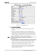
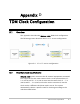
Table Of Contents
- WinLink(TM) 1000 Rev 3.0
- Notice
- Quick Start Guide
- Contents
- List of Figures
- List of Tables
- 2 Installation and Setup
- 3 Configuration
- 4 Operation
- 5 Diagnostics and Troubleshooting
- A Wiring Specifications
- B Mast and Wall Installation
- C Link Budget Calculator
- D TDM Clock Configuration
- Index

External clock requirements D-1
Appendix D
TDM Clock Configuration
D.1 Overview
This appendix describes the WINLink 1000 TDM clock configuration.
The following picture describes the E1 or T1 service configuration.
Figure D-1. E1 or T1 service configuration
D.2 External clock requirements
WINLink 1000 system assumes that all external equipments connected
to a single site use the same transmit clock. In the picture above, E1 –
1 in (site A) and E1 – 2 in (site A) must use the same clock. E1 – 1 in
(site B) and E1 – 2 in (site B) must also use the same clock, but this
clock can be a different clock that used in site A. The system
automatically selects a specific trunk for clocking according to the
rules described below.