
User's Manual
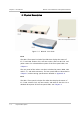
Table Of Contents
- WinLink(TM) 1000 Rev 3.0
- Notice
- Quick Start Guide
- Contents
- List of Figures
- List of Tables
- 2 Installation and Setup
- 3 Configuration
- 4 Operation
- 5 Diagnostics and Troubleshooting
- A Wiring Specifications
- B Mast and Wall Installation
- C Link Budget Calculator
- D TDM Clock Configuration
- Index

Chapter 1 Introduction WinLink 1000 Installation and Operation Manual
1-4 Physical Description
1.2 Physical Description
Figure 1-2. WinLink 1000 Units
IDU-E
The IDU-E front panel includes five LEDs that display the status of
E1/T1 and LAN, wireless link, self-test results, ODU-to-IDU link, and
power status. For a detailed description of the front panel LEDs, see
Chapter 4
.
The rear panel of the indoor unit (IDU) includes the power, WAN, LAN
and E1/T1, and ODU connectors. The rear panel LEDs are described in
Chapter 4
, and the wiring specifications detailed in
Appendix A
.
IDU-C
The IDU-C front panel includes four LEDs that display the status of
E1/T1and, wireless link, self-test results, and ODU-to-IDU link. For a
detailed description of the front panel LEDs, see
Chapter 4
.