
User's Manual

WinLink Technical Support C-135
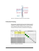
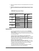
Expected Signal Level for AIND radios
Use the Link Budget Calculator utility supplied on the WinLink™
Manager Software CD-ROM to calculate the expected performance of
the WinLink™ wireless link. The utility allows you to determine the RSS
of the link and number of E1/T1 services available at a specified
distance. In all-indoor type installations, a long transmission line (RF
cable) between the radio and antenna will be used; oftentimes over
100’. In this case the attenuation (RF loss) of the cable must be
determined (for both sides) and entered as a dB loss in the Link
Budget calculator. In many cases, a larger antenna is necessary to
compensate for this transmission line loss.
Andrew LDF and AVA cables are good for minimizing loss.
Performing WinLink AIND Alignment
The supervisor of the antenna alignment is situated at the receive site
with the Spectrum Analyzer.
Equipment Setup
To set up the antenna alignment equipment:
1. Coarsely align the two antennas. Use the compass readings taken
during the Site Survey to point the antennas in the correct
direction.
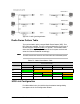
2. Connect the equipment as shown in Figure C-1 but connect a
spectrum analyzer in place of the remote WinLink-AIND.
3. Turn on the CW transmit signal from site A (from the WinLink
NMS).
4. At site B, tune the SA to the frequency transmitted.
5. Increase the SA sensitivity according to the expected receive
signal.
Aligning the antennas
When one antenna is moved, the opposite site is passive. Move the
antennas very slowly.
Note
NoteNote
Note