Chapter 6 Monitoring and Testing the Link The WinLink™ 1000 Manager software enables you to monitor the link, as well as perform Loopback tests. It also provides a handy Link calculator utility for calculating the expected performance of the wireless link and the possible RF and antenna configurations for a specific link range.
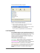
The Get Link Information dialog box appears: Figure 6-1: Get Link Information Dialog Box 2. Select or deselect the data options. If the file is to be sent to Technical Support leave all options checked. 3. Click File Path to specify the folder in which you want to save the file and then click Start to save the information. The file is saved in the specified folder as Link Information.txt Link Compatibility Link Compatibility indicates the version compatibility via software traps.
versionsIncompatibility - different software versions were detected that are not compatible. User needs to perform local upgrades. Table 6-2: Link Compatibility Trap Messages Link State Link Link Status State text Color fullCompatibility Active Green restrictedCompatibility Active - SW Version mismatch softwareUpgradeRequired versionsIncompatibility Site Description Site Link Status Desc.
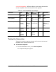
Figure 6-2: Loopback dialog box 2. From the Local or Remote drop-down box, select a loopback that you intend to run, and click OK. A confirmation message appears. 3. Click OK to activate a loopback. This activates selected loopback. A loopback status arrow in the Main menu turns green to indicate an active loopback. To deactivate a loopback: • From the From the Local or Remote drop-down box of the Loopbacks dialog box, select None and click OK.
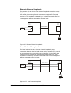
E1/T1 Interface Testing Equipment Local ODU Management Station Figure 6-3: Local External Loopback Remote Internal Loopback Remote internal loopback can be set to an internal loopback to test connection between the local and remote units, the local E1/T1 port and its connection to the local side user equipment. In this mode, data coming from the local unit is looped back to it. This loopback is initiated in band from a management station connected to the local unit.
Remote External Loopback The remote unit can be set to an external loopback to test the remote E1/T1 port and its connection to the remote side user equipment. In this mode, data coming from the remote user equipment is looped back to it. This loopback is initiated by an in band command sent from a management station connected to the local unit.
Reinstalling/Realigning the Link It may be necessary to reinstall the link if the ODUs need to be realigned. Note: Activating Install Mode causes both sites to go into install mode, causing disruption in service for approximately fifteen seconds. To reinstall the link: 1. From the Configuration menu, choose a site. The Configuration dialog box opens. 2. In the Configuration dialog box, click the Install Mode button. A message box asking if you want to enter install mode appears. 3.
Figure 6-7: WinLink™ 1000 - Link Budget Calculator Performance Monitoring Performance Monitoring constantly monitors traffic over the radio link and collects the following statistics data: • • • • Site 1/Site 2 received traffic rate (in Mbps) Site 1/Site 2 received frames rate (in Mbps) Radio signal strength (in dBm) Error (Blocks). WinLink™ 1000 monitors the Air interface, ETH ports, and TDM trunks. It does so continuously, even when the WinLink™ 1000 Manager is not connected.
The Monitor Log The Monitor log records performance statistics for predefined intervals. You can save the monitor log to a text file, as well as display the information in an on-screen report. Saving the Monitor Log You can save the recorded Monitor log statistics to a text file. To save the monitor log: 1. From the Tools menu, choose Preferences. The Preferences dialog box appears: Figure 6-8: Preferences dialog box 2. Click the Monitor Tab. 3. Select the file to save. 4.
Viewing Performance Reports The Performance Monitor Report displays performance views of each of the interfaces3: Figure 6-9: Performance Monitoring Report window Several performance data occurrences are collected for each of the interfaces (ES, SES, and UAS), as well as Specific data per Interface type (e.g., TX and RX bytes for Ethernet). For the Air Interface, user defined thresholds data are collected. Refer to 3 Ethernet performance is not collected in PoE systems.
Table 6-3 and Table 6-4, Performance Monitoring Report Toolbar. Data is collected and selectively displayed based on three time intervals as selected by the Interval radio buttons: • Current (t=0) • 15 minutes Intervals • Daily. UAS – This parameter counts the time the air link was not providing any service. There are several potential reasons for this situation; one of the sites has a power failure, high interference, maintenance operation, etc.
Table 6-3: Explanation of performance data Data type Reported Value Explanation Generic PM Data UAS – Unavailable Seconds Seconds in which the interface was out of service. ES – Error Second The number of seconds in which there was at least an error block. Note that notation of an error block is different per interface. SES – Severe Error Second The number of seconds in which the service quality is low (the actual BBER ratio varies per interface).
Data type Ethernet Interface PM Data Reported Value Explanation BBER Threshold The BBER Threshold value counts the number of seconds in which the Background Block Error Ratio (BBER) exceeds the specified threshold. Note, that the system is design for excellent quality of service with BBER of less then 1%. (at 1% BBER expected TDM BER is less than 1E-6.
Figure 6-10: Threshold configuration dialog box The Events Log The Events log records system failures, loss of synchronization, loss of signal, and other events as described in the following table: WinLink User and Installation Guide Version 1.
Table 6-5: Alarms and Information Messages Message Description Radio Link – Sync Radio link is synchronized Radio Link – Out Of Sync Radio link lost synchronization Link Has Been Reset ODU was reset due to internal problem TDM Interface – Normal TDM interface is operating properly TDM Interface – LOS Loss of Signal is reported by TDM interface TDM Interface – AIS Alarm Indication Signal is reported by TDM interface TDM Interface – Loopback A loopback is active on TDM interface Link Resetting
Figure 6-11: Events Log Display Setting the Events Preferences You can define a color for the traps to be displayed in the Active Alarms screen, according to the severity of the event. The severity is predefined. To set the trap color: 1. From the Tools menu, choose Preferences. The Preferences dialog box appears. 2. Click the Events Tab: WinLink User and Installation Guide Version 1.
Figure 6-12: Preferences dialog box 3. Select the Event priority type and click on the button. A color chart opens. 4. Select the desired color. 5. Repeat for all the trap types. To set the trap background color: • Click Background Color to change the text background. To reset the trap colors: • Click Reset Settings to return to the default color settings. Saving the Events Log You can save recorded events in an Events log text file.
4. Click the check box to open the file for saving. button and in the Select File dialog box indicate in 5. Click the which folder and under what name the alarm log file is to be saved, and click OK. Error Detection and Alarms WinLink™ Error detection and Alarms detect compatibility problems, fault conditions of the radio or user links, and subsequently initiates alarms to alert the user.
Figure 6-13: Active Alarms Summary The following table provides an explanation of the command buttons. Table 6-6: Active Alarms command buttons Action Save Saves the alarms in CSV or text format for further analysis. Refresh Reads the alarms from the ODU, and displays the alarms. Site Selects site for the active alarms. Close Closes the active alarm window. Remote Power Fail Indication Remote power fail indication indicates to one side that the other side has had a power failure.
Chapter 7 Security WinLink™ 1000’s integrated advanced encryption support provides enhanced air interface security for carriers and private networks by ensuring user data protection with one of the most sophisticated commercially available combined encryption and authentication techniques, CCM/AES. This technique combines message authentication (preventing anti-spoofing and replay protection) with commercial encryption, and complies with the IEEE 802.11i (phase iii) security recommendations.
Changing the Link Password The Radio Link is encrypted using the Advanced Encryption System (AES) using a 128 bit dynamic key. During the installation process, you must enter a Link Password. An Initial encryption key is then generated. Each time a link is established, the system validates the Encryption key. If the validation fails, the link is established but no service or configuration is allowed. In this state, you can change the link password for each of the sites.
To enter the key password: 1. From the Configuration dialog box, select the Security tab. 2. Click Change next to the Link Password field box. 3. The Change Link Password dialog box appears. 4. Click the Forgot Link Password button. The Key Link Password dialog box appears. 5. Type the key link password. 6. A new link password may now be set. WinLink User and Installation Guide Version 1.
Chapter 8 Diagnostics and Troubleshooting Use the following tables to diagnose any faults in the system. Table 8-1: Troubleshooting Symptom Remedy No power Verify that AC power is connected to the IDU. Verify that the ODU cable is properly wired and connected. No signal Complete the installation procedure from the management software. Verify the ODU alignment. Check that the radio configuration of both site A and site B units are the same (channel and SSID).
LED Status Remedy Orange Check that the system is not in loopback mode. Check the site B IDU ports and cables and site B external equipment. Red Check the site A IDU ports, cables and external equipment. Replacing an ODU Prior to any action verify that both ODUs have the same software version (Configuration > Configure site xxxxxx>Inventory). If one ODU has an old software version, perform a software upgrade.
Q: When using the WinLink™ 1000, what is the potential for interference between our system and other cellular or wireless Networks devices? A: The WinLink™ 1000 is a robust system. However since it operates in unlicensed ban, interference can occur. Nevertheless, the fact that we can manually set the frequency to one of 5 (6) non-overlapping channels gives you the flexibility to find a clean channel.
Q: Can I use the WinLink™ 1000 with any vendor’s external antenna? A: RADWIN supplies the WinLink™ 1000 external ODU with an N-type typical connector. Any vendor’s external antenna that is of the same type and of equal or less directional gain as an antenna that RADWIN authorized with its specific external ODU product, can be used. This is provided that it can be cascaded to our external unit.
Q: Can I use any category 5e cable in order to connect the IDU and ODU? A: The cable should be suitable for outdoor use, and shielded Category 5e. Q: What are the BER values expected in the WinLink™ 1000 link? A: 10-11 (according to BER sensitivity threshold) Q: Does WinLink™ 1000 use DSSS technique? A: No, WinLink™ 1000 uses the advanced OFDM technique. Q: What are the advantages of the WinLink™ 1000 solution over other possible alternatives (e.g., wireline, wireless, etc.
Online Help Online help can be accessed from the Help menu on the main screen of the WinLink™ 1000 Manager. Figure 8-1: Online Help for WinLink™ 1000 Technical Support Technical support for this product can be obtained from the local VAR, Integrator or distributor from whom it was purchased. For further information, please contact the WinLink™ distributor nearest you or one of RADWIN's offices worldwide (click www.Radwin.com). WinLink User and Installation Guide Version 1.
Appendix A Wiring Specifications The ODU-IDU cable is shielded/outdoor CAT-5, 4 twisted-pair 24 AWG FTP, terminated with RJ-45 connectors on both ends. It is covered by a cable gland on the ODU side for hermetic sealing.
Table A-2: E1/T1 Connector Pinout Pin Function 4,5 Receive (input) 1,2 Transmit (output) LAN Port The LAN 10/100BaseT interface terminates in an 8-pin RJ-45 connector, wired in accordance to Table A-3.
IDU-C Connectors IDU-C DC Power Terminal Table A-5: Terminal Block 3-pin -48VDC Pin Right Center Left Function + Chassis – IDU-C Alarm Connector Table A-6 lists the IDU-C Alarm connector pinout.
Alarm Connector 10 to 50 VDC alarm voltage +ve 1 Input 1 -ve 6 +ve 2 Input 2 -10 to -50 VDC alarm voltage - ve 7 N/C 3 1 N/O 4 Ext. current limit resistor Output Alarm LED Ext. DC Power COM 8 Ext. current limit resistor N/O Output Alarm Buzzer 7 2 Ext. DC Power COM 9 Figure A-1: Example for connecting the alarm connector WinLink User and Installation Guide Version 1.
PoE Alarm Connector The following table lists the PoE Alarm connector pinout. Table A-7: PoE Alarm Connector (Dry-Contact) Pin I/O Description 1 NA NA 2 NA NA 3 Output 1 Normally Closed 4 Output 1 Normally Open 5 Output 2 Normally Open 6 NA NA 7 Output 2 Normally Closed 8 Output 1 Common 9 Output 2 Common IDU-R and IDU-AL Alarm Connectors The following table shows the pinout for the IDU-R and IDU-AL Alarm Connectors.
O-PoE to PC LAN Cable When connecting the O-PoE ETH port cable directly to PC, a crossed LAN CAT-5, 4 twisted-pair 24 AWG FTP, terminated with RJ-45 connectors on both ends must be used.
Appendix B Mast and Wall Installation The ODU or O-PoE can be mounted on a mast or a wall. Ensure that the unit is oriented so that the cable connectors are at the bottom. (If they are on top, water may penetrate into the unit causing damage.
Mounting WinLink™ 1000 on a Mast Figure B-4: Mounting on a Mast WinLink Technical Support B-130
WinLink Technical Support B-131
Mounting WinLink on a Wall Figure B-5: Mounti ng on a Wall WinLink Technical Support B-132
Mounting an External Antenna The optional external antenna can be mounted on a mast. External Antenna Mounting Kit Contents The external antenna mounting kit includes the following items: • • • • • • • Twelve flat washers Eight spring washers Eight hex nuts Four bolts One U-bracket One pivoting bracket Two metal strap clamps. To install external antenna on the mast: 1. Attach the U-bracket to the back of the antenna using four flat washers, four spring washers and four hex nuts. 2.
Appendix C AIND Alignment Use this procedure when using the all indoor system WinLink-ANID or manually aligning two WinLink units. To achieve the best benefit and link budget from the WinLink™ 1000 installation, the link antennas must be aligned; the two antennas should exactly face each other. In order to achieve the best performance, the line of sight must be as clear as possible with no obstructions between the two sites.
Expected Signal Level for AIND radios Use the Link Budget Calculator utility supplied on the WinLink™ Manager Software CD-ROM to calculate the expected performance of the WinLink™ wireless link. The utility allows you to determine the RSS of the link and number of E1/T1 services available at a specified distance. In all-indoor type installations, a long transmission line (RF cable) between the radio and antenna will be used; oftentimes over 100’.
To align the antennas: 1. Slowly move the site B antenna azimuth axis (the elevation axis should be locked) until you see the best signal on the SA Lock the azimuth axis. 2. Slowly move the site A antenna azimuth axis (the elevation axis should be locked) until you see the best signal on the SA. 3. Lock the azimuth axis. 4. Slowly move the site B antenna elevation axis (the azimuth axis should be locked) until you see the best signal on the SA. Lock the elevation axis. 5.
RSS: –84 dBm minimum There are cases when there is no line of sight, but still the link is of an acceptable quality. If the link is not within the acceptable limit, see Troubleshooting. Troubleshooting If the link is not within the acceptable limit as defined in Evaluating the Link, check the following: • • • • • • • WinLink Verify that both antennas have the same polarization (horizontal/vertical). Check all the WinLink-AIND cable connectors for faulty connections.
Appendix D Antenna An antenna is the radiating and receiving element from which the radio signal, in the form of RF power, is radiated to its surroundings and vice versa. The transmission range is a function of the antenna gain and transmitting power. These factors are limited by country regulations. The WinLink may be operated with an integrated antenna attached to the ODU unit, or with an external antenna wired to the ODU via an Ntype connector.
The Parabolic dish antenna is a high-gain, reflector antenna used for radio, television, and data communications. The relatively short wavelength of electromagnetic (radio) energy at these frequencies allows reasonably sized reflectors to exhibit the very desirable highly directional response for both receiving and transmitting. Parabolic Dish Antenna Used for 2.4 GHz applications. Due to the large size, the grid design minimizes weight and windloading.
Appendix E Hub Site Synchronization When several units are collocated at a common hub site, interference may occur from one unit to another. ODU units are supplied with special hardware for the collocation of up to eight units from a central site. Using a method called Hub Site Synchronization (HSS) an external cable is connected from the master to all collocated ODUs; this cable carries pulses sent to each ODU, which synchronize their transmission with each other.
Figure E-2: Collocated units using Hub Site Synchronization Collocation Planning WinLink provides a collocation planning tool and calculator for planning the placement of multiple units at the same site. It provides physical guidelines for each specific installation scenario. The tool can be used prior to installation to define and verify the distance between the collocated units and their direction, polarization and TPC adjustment.
Appendix G RF Exposure WARNING: The antennas used for the following transmitters must be installed to provide a separation distance of at least 200 cm from all persons and must not be co-located or operating in conjunction with any other antenna or transmitter. Note: For products having minimum safety distance values that are higher than 200 cm, the higher value must be considered.
4. Tighten the protective seal that is on the prepared cable over the RJ-45 connector. 5. Repeat for all ODUs that are to be collocated at the hub site. The next ODU to be connected is inserted to SYNC 2, followed by SYNC 3 and so on.
Figure E-5: HSS Typical Application Radio Frame Pattern Table The synchronization pulse is termed Radio Frame Pattern (RFP). Four RFP pulses are available. The RFP is selected depending on the type of services that the complete system is to provide - see the table below. Select the RFP that gives you the Best Fit for the system services and select the Channel Bandwidth accordingly. Note The RFP must be the same for each link within the collocated system.
Figure E-6: Hub Site Synchronization Settings dialog box The Synchronization Status dialog box displays the current status of each side of the link.
Table E-3: External Pulse Status Status Description Text Color Not Detected Sync pulses not detected Green Generating Unit is HSM and is generating RFP pulses Green Generating and Detected Unit is HSM and generating RFP pulses and is also receiving pulses from another unit. Incorrect configuration. Red Generating and Improper Detected Unit is HSM and generating RFP pulses and is also receiving incorrect pulses from another unit. Incorrect configuration.
WinLink™ 1000 gives error messages and tool tips if the system is configured with mismatches. Figure E-7: Hub Site Configuration dialog box Site Configuration For units that support HSS, the Hub Site Sync option appears in the Air Interface section and displays the current HSS of the unit. Configure the unit from the Link Configuration Wizard according to the procedure described above. WinLink User and Installation Guide Version 1.
Figure E-8: Site Configuration – Hub Site Sync dialog box The following figure is displayed when the hardware does not support HSS. These units may be used as independent remote units. WinLink User and Installation Guide Version 1.
Figure E-9: HSS Not Supported WinLink User and Installation Guide Version 1.
Appendix F BRS Installation Procedure BRS Link Activation In accordance with 2.5 GHz standard, WinLink-BRS systems links must be activated before use. This is done at both ODUs independently before installation on site. Both ODUs must be configured the same. To Activate a BRS Link 1. Install WinLink Manager software as usual. 2. When the Manager Main Screen is displayed it appears with the Link Status label red and showing Inactive. The Link Configuration and Link installation buttons are disabled.
Figure F-2: BRS Air Interface dialog box 4. Set the appropriate Frequency Band Plan and Bandwidth. 5. Select the required frequency band, and click Apply. 6. Click Installation Mode 7. Repeat for the remote ODU. WinLink User and Installation Guide Version 1.
Figure F-3: BRS Channel Settings Pre-Transition 8. Perform the remainder of the Installation procedure as defined in the Installation section. BRS Link Configuration The BRS link is reconfigured during the Link Installation or the Link Configuration wizards, or from the Air Interface screen. Note Both sites in a BRS Link must be configured identically. Any changes to the frequency settings cause the link to re-synchronize. A short loss of service will occur during re-synchronization.
Figure F-4: BRS Channel Settings Post-Transition WinLink User and Installation Guide Version 1.
Appendix G RF Exposure WARNING: The antennas used for the following transmitters must be installed to provide a separation distance as specified. They must not be co-located or operated in conjunction with any other antenna or transmitter. Product FCC ID F58/FCC/EXT Q3KAMWL1000 28 83 F58/FCC/INT Q3KAMWL1000 22 42 HE/F58/FCC/INT Q3KAMWL1580 22 109 HE/F58/FCC/EXT Q3KAMWL1580 28 217 HE/F58/FCC/EXT Q3KAMWL1580 32.5 364 AIND/F58/FCC/EXT/4T1 Q3KAMWL1580 32.
Appendix H Link Budget Calculator Overview The Link Budget Calculator is a utility for calculating the expected performance of the WinLink wireless link and the possible configurations for a specific link range. The utility allows you to calculate the expected RSS of the link, and find the type of services and their effective throughput as a function of the link range and deployment conditions. The Link Budget Calculator is supplied on the WinLink Manager CD.
Fade Margin (FM) the margin taken in consideration as part of the parameters needed as spare for high availability. Min level accepted by the LBC is 6dB. EIRP Tx Power + Antenna Gain (*) – in some products they are limited to a max value due to local regulation and type approval. Example 1 10 x Log (Value in mW) = (Value in dBm) 1W is the maximum EIRP (Tx Power + Antenna Gain (*)) that is allowed in 5.4 GHz ETSI products by ETSI regulation, (*) considering cable loss.
Figure H-2: Link Budget Screen Figure H-3: Climate and Terrain Factor WinLink User and Installation Guide Version 1.
Figure H-4: Geographical Conditions Figure H-5: Fresnel Zone Using the Link Budget Calculator The Link Budget Calculator is composed of one table where all the link parameters are defined. WinLink User and Installation Guide Version 1.
To calculate the link budget 1. Select your system product from the dropdown list of products. 2. Select the rate from the dropdown list. The rate defines the airinterface rate in Mbps. The system operates in TDD mode and has overhead of the air-interface protocol and therefore the accurate actual throughput is provided in the ‘Service’ Row and the effective Ethernet throughput is provided in the ‘Ethernet Rate’. 10. Note Throughput can be decreased as a function of range due to propagation delay.
Appendix I Product Specification Table Table I-1: Product Specification Table Band Product 2.3 Frequency (MHz) Min Max 2312 2387 Transmit Power (dBm) Antenna Gain (dBi) EIRP (dBm / Watt) DFS ACS Min Max 5 16 16 24 39 / 7.9 + -4 -4 24 19 / 0.1 + Step TPC 1 WL1000-ODU/F23/HP/EXT 2 WL1000-ODU/F24/ETSI/EXT 2412 2472 5 3 WL1000-ODU/F24/HP/EXT 2312 2472 5 + 12 16 24 39 / 7.9 4 WL1000-ACCESS/F24/HP/EXT 2312 2472 5 + 12 16 24 39 / 7.
Band Product Frequency (MHz) Min Max Transmit Power (dBm) Step TPC Min Max Antenna Gain (dBi) EIRP (dBm / Watt) DFS ACS 25 WL1000-ODU/F54/ETSI-HG/EXT 5500 5700 20 + -3 3 28 30 / 1.0 + + 26 WL1000-HE/ODU/F54/ETSILG/EXT 5500 5700 20 + -3 15 28 42 / 15.8 + + 27 WL1000-ODU/F54/HP/EXT 5500 5700 20 + 4 18 28 45 / 31.6 + 28 WL1000-HE/ODU/F54/HP/EXT 5500 5700 20 + 4 23 28 50 / 100 + 29 WL1000-HE/ODU/F54/HP/INT 5500 5700 20 + 4 23 22 45 / 31.
Appendix J Lightning and Grounding Guidelines The WinLink™ Lightning protection system consists of the following components, as described below: • Individual Grounding for each Indoor/Outdoor unit • External Primary Surge Suppressor unit for the CAT-5 Outdoor cable • Internal ESD protection circuits over the Power/Telecom lines Grounding for Indoor/Outdoor Units ODU (Out Door Unit) Grounding WinLink™ uses a Shielded CAT-5 cable to interconnect the Outdoor (ODU) and Indoor (IDU) units.
cable. 3rd pary protectors may be used such as Motorola’s 300SS, Hyperlink’s HGLN-CAT5, or Sixnet’s SP-ETH-2 Internal ESD Protection circuits WinLink™ is designed to meet the ETSI/FCC/Aus/NZ/CSA EMC and Safety requirements. To fulfill these requirements, the system’s Telecom lines at the ODU/IDU are Transformer-isolated and include internal ESD (Electro-Static-Discharge) Protection circuits. WinLink User and Installation Guide Version 1.
Appendix K MIB Reference Introduction About the MIB The RADWIN MIB is a set of API’s that can be used to control the RADWIN management functions via external applications. The MIB is divided into a public and a private API groups. The private API group is owned by RADWIN and supplements the public group. The RADWIN WinLink™ 1000 supports the variables of RFC-1213 (MIB II) public MIB set out in table Table K-2 below.
Interface API System Configuration The system includes SNMP agents on both ODU’s. Each agent can be accessed only from the local side of the link. The management station can access the SNMP agent using the Ethernet port over any SNMP/UDP/IP network. The local SNMP agent contains data on both the local and remote ODU’s and IDU’s. Both agents communicate with each other over the air using a proprietary protocol. Each ODU has a single MAC and IP address.
• • • A common practice is to configure the remote unit first and then to configure the local unit only if there was no problem in remote configuration. For some of the configuration parameters additional action must be taken before the new value is loaded. Please refer to the operation in the parameters description. Some of the MIB parameters values are product dependent. It is strongly recommend using the Winlink™ 1000 ManagerWinlink™ 1000 Manager Application for changing these values.
Private Products WinLink™ 1000 ODU Admin Service Ethernet Bridge Air IDU Admin Service TDM General Table K-1: Top Level Sections of the private MIB Products MIB The products MIB section contains the definition of the Object IDs for each hardware configurations of the ODU. Supported hardware configurations are for integrated and external antennas. ODU MIB The ODU MIB is divided into five sub sections: Admin, Service, Ethernet, Bridge and Air.
The Air Section is includes, in the top level, configuration data such as frequency and rate and a sub-section for air interface performance data. IDU MIB The IDU MIB is divided into three sub sections: Admin, Service and TDM. The Admin section includes data about the software and hardware revisions of the product. Note the IDU is managed via the ODU and therefore no IP configuration is available for this unit.
Supported Variables from the RFC 1213 MIB Table K-2 Supported RFC 1213 Variables Type Description OID ifIndex .1.3.6.1.2.1.2.2.1.1.x Integer RO A unique value for each interface. Its value ranges between 1 and the value of ifNumber. The value for each interface must remain constant at least from one re-initialization of the entity's network management system to the next reinitialization. ifDescr .1.3.6.1.2.1.2.2.1.2 DisplayString RO A textual string containing information about the interface.
Description OID Type ifOutUcastPkts .1.3.6.1.2.1.2.2.1.17.x Counter RO The total number of packets that higher-level protocols requested be transmitted to a subnetwork-unicast address, including those that were discarded or not sent. ifOutNUcastPkts .1.3.6.1.2.1.2.2.1.18.x Counter RO The total number of packets that higher-level protocols requested be transmitted to a nonunicast (i.e., a subnetwork-broadcast or subnetwork-multicast) address, including those that were discarded or not sent.
MIB Parameters List Access Table K-3Private MIB Parameters List Description Name OID Type winlink1000OduAdmProductType 1.3.6.1.4.1.4458.1000.1.1.1 DisplayString RO ODU configuration description. winlink1000OduAdmHwRev 1.3.6.1.4.1.4458.1000.1.1.2 DisplayString RO Hardware Revision of the ODU. winlink1000OduAdmSwRev 1.3.6.1.4.1.4458.1000.1.1.3 DisplayString RO Software Revision of the ODU. winlink1000OduAdmLinkName 1.3.6.1.4.1.4458.1000.1.1.4 DisplayString RW Link Name.
Access Description Name OID Type winlink1000OduReadWriteCommunity 1.3.6.1.4.1.4458.1000.1.1.16 DisplayString RW The Read/Write Community String. This variable always returns ***** when retrieving its value. It is used by the element manager to change the Read/Write Community String. The SNMP agent accepts only encrypted values. winlink1000OduTrapCommunity 1.3.6.1.4.1.4458.1000.1.1.17 DisplayString RW The Trap Community String.
Type Access OID Name Description winlink1000OduEthernetIfTable N/A ODU Ethernet Interfaces Table. winlink1000OduEthernetIfEntry N/A Table entry. INDEX { winlink1000OduEthernetIfIndex } winlink1000OduEthernetIfIndex 1.3.6.1.4.1.4458.1000.1.3.2.1.1 Integer RO If Index corresponding to this Interface. winlink1000OduEthernetIfAddress 1.3.6.1.4.1.4458.1000.1.3.2.1.5 DisplayString RO MAC address of the ODU. winlink1000OduEthernetIfAdminStatus 1.3.6.1.4.1.4458.1000.1.3.2.1.
Access Description Name OID Type winlink1000OduAirDesiredRate 1.3.6.1.4.1.4458.1000.1.5.2 Integer RW This parameter is deprecated and read-only. Desired Rate of the air interface. This value is relevant for a Channel Bandwidth of 20 MHz only. For 5 & 10 MHz winlink1000OduAirSSID 1.3.6.1.4.1.4458.1000.1.5.3 DisplayString RW This parameter is reserved to the element manager provided with the product. winlink1000OduAirTxPower 1.3.6.1.4.1.4458.1000.1.5.
Name OID Type Access winlink1000OduAirCurrentTxPower 1.3.6.1.4.1.4458.1000.1.5.12 Integer RO Current Transmit Power in dBm. This is a nominal value. The actual transmit power includes additional attenuation. For further details refer to the User Manual. winlink1000OduAirMinFrequency 1.3.6.1.4.1.4458.1000.1.5.13 Integer RO Minimum center frequency in MHz. winlink1000OduAirMaxFrequency 1.3.6.1.4.1.4458.1000.1.5.14 Integer RO Maximum center frequency in MHz.
Name OID Type Access winlink1000OduAirMaxTxPower 1.3.6.1.4.1.4458.1000.1.5.23.1.2 Integer RO winlink1000OduAirChannelBandwidth 1.3.6.1.4.1.4458.1000.1.5.24 Integer RW Channel bandwidth in KHz. A change is effective only after device reset. Description Maximum transmit power in dBm. winlink1000OduAirChannelBWTable N/A Table of channel bandwidths. winlink1000OduAirChannelBWEntry N/A Channel bandwidth table entry. INDEX { winlink1000OduAirChannelBWIndex } winlink1000OduAirChannelBWIndex 1.3.
Name OID Type Access winlink1000OduAirHssExtPulseStatus 1.3.6.1.4.1.4458.1000.1.5.40.4 Integer RO Hub Site Synchronization external pulses detection status. winlink1000OduAirHssExtPulseType 1.3.6.1.4.1.4458.1000.1.5.40.5 Integer RO Hub Site Synchronization external pulses type. winlink1000OduAirHssDesiredExtPulse Type 1.3.6.1.4.1.4458.1000.1.5.40.6 Integer RW Hub Site Synchronization desired external pulses type.
Type Access OID Name Description winlink1000OduPerfMonIntervalEntry N/A This is an entry in the Interval Table. INDEX {ifIndex winlink1000OduPerfMonIntervalIdx RO This table is indexed per interval number. Each intervalis of 15 minutes and the oldest is 96. winlink1000OduPerfMonIntervalUAS RO The current number of Unavailable Seconds per interval. winlink1000OduPerfMonIntervalES RO The current number of Errored Seconds per interval.
Name OID Type Access winlink1000OduPerfMonAirCurrMinTSL 1.3.6.1.4.1.4458.1000.1.6.4.1.5 Integer RO The current Min Transmit Signal Level starting from the present 15 minutes period. winlink1000OduPerfMonAirCurrMaxTSL 1.3.6.1.4.1.4458.1000.1.6.4.1.6 Integer RO The current Max Transmit Signal Level starting from the present 15 minutes period. winlink1000OduPerfMonAirCurrTSLThre 1.3.6.1.4.1.4458.1000.1.6.4.1.
Type Access OID Name Description winlink1000OduPerfMonAirDayRSLThre sh1Exceed RO The number of seconds Receive Signal Level exceeded the RSL1 threshold per Day. winlink1000OduPerfMonAirDayRSLThre sh2Exceed RO The number of seconds Receive Signal Level exceeded the RSL2 threshold per Day. winlink1000OduPerfMonAirDayMinTSL RO The current Min Transmit Signal Level per Day. winlink1000OduPerfMonAirDayMaxTSL RO The current Max Transmit Signal Level per Day.
Type winlink1000OduPerfMonTdmCurrEntry winlink1000OduPerfMonTdmCurrActive Seconds Access OID Name Description N/A This is an entry in the Current Interval Table. INDEX {ifIndex } 1.3.6.1.4.1.4458.1000.1.6.10.1.1 Gauge RO The parameter indicates whether the TDM service was active. Under TDM backup link winlink1000OduPerfMonTdmIntervalTab le N/A This table defines/keeps the counters of the current 15 min interval.
Type winlink1000OduAgnCurrAlarmEntry Access OID Name Description N/A Entry containing the details of a currently RAISED trap. INDEX { winlink1000OduAgnCurrAlarmCounter } winlink1000OduAgnCurrAlarmCounter 1.3.6.1.4.1.4458.1000.1.7.3.2.1.1 Integer RO A running counter of active alarms. The counter is incremented for every new RAISED trap.It is cleared after a device reset. winlink1000OduAgnCurrAlarmSeverity 1.3.6.1.4.1.4458.1000.1.7.3.2.1.2 Integer RO The current Alarm severity.
Access Description Name OID Type winlink1000IduSrvServices 1.3.6.1.4.1.4458.1000.2.2.4 ObjectID RO This parameter is reserved to the element manager provided with the product. winlink1000IduSrvActiveTrunks 1.3.6.1.4.1.4458.1000.2.2.6 Integer RO A bitmap describing the currently open TDM trunks. winlink1000IduSrvAvailableTrunks 1.3.6.1.4.1.4458.1000.2.2.8 Integer RO A bitmap describing the TDM trunks that can be opened in the current configuration.
Name OID Type Access winlink1000IduSrvEthThroughput 1.3.6.1.4.1.4458.1000.2.2.14 Gauge RO winlink1000IduSrvEthMaxInfoRate 1.3.6.1.4.1.4458.1000.2.2.15 Integer RW Holds the maximum bandwidth (kbps) to be allocated for ethernet service. Value of zero means that ethernet service works as best effort. The maximum value is product specific Description Current available Ethernet service throughput in bps. winlink1000IduEthernetIfTable N/A IDU Ethernet Interfaces Table.
Type Access OID Name Description winlink1000IduTdmCurrentTable N/A IDU TDM Links Statistics Table. winlink1000IduTdmCurrentEntry N/A Table entry. INDEX { winlink1000IduTdmCurrentIndex } winlink1000IduTdmCurrentIndex RO Table index (Same as winlink1000IduTdmLineIndex). winlink1000IduTdmCurrentBlocks 1.3.6.1.4.1.4458.1000.2.6.7.1.101 Counter RO Number of correct blocks transmitted to the line. winlink1000IduTdmCurrentDrops 1.3.6.1.4.1.4458.1000.2.6.7.1.
Access Description Name OID Type winlink1000IduTdmJitterBufferSizeEval 1.3.6.1.4.1.4458.1000.2.6.17 Integer RW TDM Jitter Buffer Size for evaluation. The value must be between the minimum and the maximum TDM Jitter Buffer Size. The units are 0.1 x millisecond. winlink1000GeneralTrapDescription 1.3.6.1.4.1.4458.1000.100.1 DisplayString RO Trap's Description. Used for Trap variables. winlink1000GeneralTrapSeverity 1.3.6.1.4.1.4458.1000.100.2 Integer RO Trap's Severity.
Trap parameters list Table K-4 Trap List Name ID Severity Description trunkStateChanged 1 normal Indicates a change in the state of one of the TDM trunks. Raised by both sides of the link. Contains 3 parameters: 1 - Description: TDM Interface %n - %x. 2 - %n: Is the trunk number. 3 - %x: Is the alarm type and can be one of the following: Normal, AIS, LOS, Loopback. linkUp 2 normal Indicates that the radio link is up.
Name ID Severity Description transmittingOnChannel 14 normal Indicates that the ODU is transmitting on channel. Contains a single parameter, which is its description: 1 - Description: Transmitting on channel %n GHz. %n Is the channel frequency in GHz. scanningChannels 15 normal Indicates that the ODU is scanning channels. Contains a single parameter, which is its description: 1 - Description: Channel scanning in progress.
Name ID Severity Description bitFailedAlarm 107 critical The trap is sent in case there is no way to recover from the situation. Contains two parameters: 1 - Description: ODU power up built in test failed. Error code is: %n. 2 - %n number. wrongConfigurationLoadedAlarm 108 major The trap is sent in case there is a way to recover from the situation. Contains two parameters: 1 - Description: Wrong configuration loaded. Error code is: %n. 2 - %n number.
Name ID Severity Description linkLockUnautorizedODU 123 major Indicates that the ODU is unautorized. Contains a single parameter which is its description: 1 - Description: Unauthorized ODU connection rejected. tdmServiceClear 200 normal Indicates that TDM Service fault is cleared. Contains a single parameter, which is its description: 1 - Description: TDM Service Normal. ethServiceOpened 201 normal Indicates that Ethernet Service has been opened.
Name ID Severity Description hssMultipleSourcesDisappearedClear 218 normal Indicates that multiple sync pulse sources disappeared. Contains a single parameter which is its description: 1 - Description: HSS multiple sync pulse sources disappeared. hssSyncToProperSourceAchievedClear 219 normal Indicates that synchronization to a proper Sync source was achieved. Contains a single parameter which is its description: 1 - Description: HSS sync pulse - Up.
Appendix L Alarms System Specification Alarms System Specification The three products, IDU-E-AL, IDU-C and PoE-8 have a dry contact alarm relay through a 9 or 25 pin connector. There are two alarm types – input and output. 1. Input alarm The input alarms are raised by events from external equipment such as a fire warning or an air conditioner failure. 2. Output alarm Output alarms are generated by the external link, for example from a sync loss, disconnection.
Table L-1 IDU Alarms IDU Configuration Name Description Alarm On State Alarm Off State Input 1 User External Alarm User External Alarm On User External Alarm Off Input 2 User External Alarm User External Alarm On User External Alarm Off Input 3 User External Alarm User External Alarm On User External Alarm Off Input 4 User External Alarm User External Alarm On User External Alarm Off Output 1 Air Link Alarm 1. Link is Down 2. Link in Installation mode 3.
IDU Configuration IDU-C Name Description Alarm On State Alarm Off State Input 1 User External Alarm User External Alarm On User External Alarm Off Input 2 User External Alarm User External Alarm On User External Alarm Off Output 1 Air Link Alarm 1. Link is Down 2. Link in Installation mode 3. Link Authentication Problem Link is up Output 2 Equipment Alarm 1. Built in Test (BIT) Error 2. No connection to the ODU 3.
Index A Active Alarm Summary Adaptive Modulation Advanced configuration AIND All Indoor Radio Unit Air Interface configuration rate Alarm connector Alarms list of Antenna characteristics 6-112 5-65 5-72 3-28 2-17 5-71 5-65 2-18, A-125 6-112 6-109 D-138 B Backup button Band Plan Beeper muting restore Bridge configuration BRS BRS Link Activation BRS Link Configuration 5-87 5-72 F-151 5-85 5-85 5-72, 5-79 F-150 F-150 F-152 C Change password Channel select Community String change dialog box forgotten string
G Get Link Information Grid Antenna 6-95 D-139 H Hub Site Synchronization Hub Sync Clients Hub Sync Master E-140 E-143 E-143 I Icon Connectivity Encryption IDU Aging time Ethernet Bridge Fast aging mode Hub Mode IDU-2E1-AL rear panel IDU-C front panel Indicators Information messages Install mode button Installation management software sequence software wizard Inventory IP address 4-56 4-56 5-79 5-80 5-80 5-80 3-27 3-27, 3-28 2-18 6-109 5-72 5-72 3-25 3-22 3-24 3-32 5-72 5-72, 5-75 L LAN connection LAN
Pinout Fast Ethernet connector Power specifications Power supply Preferences event colors reset event colors Prerequisites A-124 2-18 3-29 6-103 6-111 6-111 3-20 Q Quality bar 3-37, 3-38, 5-63 R Radio signal strength Re-installing the Link Reselect Channel Reset factory defaults Restore button Restoring configuration 4-55 6-101 3-37, 3-38, 5-61, 5-63 5-87 5-88 5-72 5-87 S Saving Saving the Monitor Log Security configuration Service parameters Site requirements SSID WinLink User and Installation Guide