
User's Manual Part 2


WinLink 1000 Installation and Operation Manual Appendix D AIND Antenna Alignment Procedure
2. Slowly move the site A antenna azimuth axis (the elevation axis
should be locked) until you see the best signal on the SA.
Lock the azimuth axis.
3. Slowly move the site B antenna elevation axis (the azimuth axis
should be locked) until you see the best signal on the SA.
Lock the elevation axis.
4. Slowly move the site A antenna elevation axis (the azimuth axis
should be locked) until you see the best signal on the SA.
Lock the elevation axis.
5. Repeat steps 1 to 4 until the reading on the SA is equal or as close
as possible to the calculated receive signal (for Rx Power Level see
Expected Signal Level
).
When the SA reads the expected receive signal, the antennas are
aligned and there is an indication of a good link between the sites.
6. Tighten the antenna azimuth axis and elevation axis.
7. Stop the CW function. The NMS will restart the system.
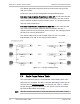
8. Connect WinLink 1000-AIND unit to external antenna. See WinLink
1000 Installation and Operation Manual for details. The operational
link is shown in
Figure 2-3
.
9. Configure WinLink 1000 NMS at both sites to operate at the pure
channel frequency found in the RF survey. WinLink 1000 is now
ready for operation.
D.3 Configuring the Link
1. Run the Installation Wizard in the WinLink 1000 Manager Software
to set the configuration of the link. Configure the link in accordance
with the parameters calculated in the Link Budget Calculator.
2. WinLink 1000 has a unique identification number, the SSID. Each
side of the link looks for its partner with the same SSID. Therefore
both sides of the link must be configured with the same SSID.
3. The WinLink 1000 link is now ready for operation.
Configuring the Link D-3