Installation and Operation Manual WinLink™ 1000 Point-to-Point Wireless Product Family Version 12 .
WinLink 1000 Point-to-Point Wireless TDM/IP Installation and Operation Manual Notice This manual contains information that is proprietary to RADWIN Ltd. ("RADWIN"). No part of this publication may be reproduced in any form whatsoever without prior written approval by RADWIN Ltd.
900 Corporate Drive, Mahwah, NJ 07430, USA Tel: 1.800.444.7234 (ext. 341) Tel: +1.201.529.1100 (ext. 341) Fax: +1.201.529.5777 Email: infousa@radwin.com RADWIN India P-13, Basement 2, Malviya Nagar, New Delhi 110017, India Tel 1: +91.11.2667.1510 Tel 2: +91.98.10303549 Email: sales@radwin-india.com FCC – User Information This equipment has been tested and found to comply with the limits for a Class B digital device, pursuant to Part 15 of the FCC Rules.
those antennas certified with the product are used. The use of any antenna other than those certified with the product is expressly forbidden in accordance to FCC rules CFR47 part 15.204. Outdoor units and antennas should be installed ONLY by experienced installation professionals who are familiar with local building and safety codes and, wherever applicable, are licensed by the appropriate Warning government regulatory authorities.
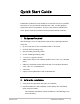
Quick Start Guide Installation of WinLink 1000 should be carried out only by a qualified technician. If you are familiar with WinLink 1000, use this guide to prepare the units for operation. If you are not familiar with WinLink 1000, please read the Installation and operation Manual carefully. 1.
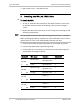
Quick Start Guide Installation and Operation Manual 3. BRS systems only - Activate the link. 3. Æ Installing the WinLink 1000 Units To install the ODU: 1. At site A, route the ODU cable from the ODU location (on the roof) to the IDU location (inside the building). The maximum length is 100m. 2. Mount the ODU unit to the mast or wall, using the mounting kit and Note mounting instructions.
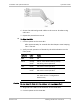
Installation and Operation Manual Quick Start Guide 6. Secure the ODU and ground cables to the mast or brackets using cable ties. 7. Repeat the procedure at site B. Æ To align the ODU: 1. Connect power to the site A IDU. After approximately 20 seconds the ODU beeper starts beeping. This is normal. 2. Verify normal operation of the IDU by the LED indications on the front panel.
Quick Start Guide Installation and Operation Manual After approximately 20 seconds the ODU beeper starts beeping. This is normal. 5. Verify normal operation of the IDU by the LED indications on the panel.
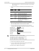
Installation and Operation Manual Quick Start Guide 11. Monitor the link quality for about 15 minutes to verify stability. 12. Connect the management station to one of the two IDUs in the link. 13. Double-click the WinLink 1000 Manager icon to start the application. 14. Click the Installation button to open the installation wizard and follow the installation steps.
Quick Start Guide Installation and Operation Manual 4. Connecting the Power Before connecting any cable, the protective earth terminals of the Warning AC/DC adapter must be connected to the protective ground conductor of the mains power cord. If you are using an extension cord (power cable) make sure it is grounded as well. Any interruption of the protective (grounding) conductor (inside or outside the instrument) or disconnecting of the protective earth terminal can make this unit dangerous.
Installation and Operation Manual Æ Quick Start Guide To connect AC power to an IDU-C: 1. Connect the power cable socket to the power connector on the WinLink 1000 front panel. 2. Connect the power cable plug to the mains outlet. The unit will be turned on automatically upon connection to the mains. Æ To connect DC power to an IDU-C A special IEC 60320 adapter for -48 VDC or -24 VDC power connection is supplied with the unit.
Quick Start Guide Installation and Operation Manual On the front panel of the IDU-C 2. Connect user hub/router or any other compatible device to the IDU RJ-45 port designated LAN. Æ On the rear panel of the IDU-E On the front panel of the IDU-C To connect user equipment to the O-PoE: 1. Connect user hub/router or any other compatible device to the port designated ETH via an outdoor shielded CAT-5e cable. To connect directly to PC LAN port, refer to Appendix A.
Contents Chapter 1. Introduction 1.1 Overview .................................................................................................. 1-1 Application....................................................................................................... 1-1 Versions........................................................................................................... 1-2 Features ........................................................................................................... 1-2 1.
Table of Contents Installation and Operation Manual Chapter 3. Operation 3.1 Turning On WinLink 1000 ......................................................................... 3-1 3.2 Controls and Indicators ............................................................................ 3-1 IDU Front Panel Indicators ................................................................................ 3-1 WAN/LAN Indicators.........................................................................................
Installation and Operation Manual Table of Contents Saving WinLink 1000 Configuration in a File ................................................... 4-29 Restoring a Configuration File ........................................................................ 4-30 4.17 Reinstalling the Link ............................................................................... 4-30 4.18 Resetting WinLink 1000 .......................................................................... 4-30 4.
Chapter 1 Introduction 1.1 Overview WinLink 1000 is a carrier-class, high capacity, Point-to-Point broadband wireless transmission system. WinLink 1000 combines legacy TDM and Ethernet services over 2.3 to 2.7 and 4.0 to 5.9 GHz bands, and is suitable for deployment in FCC, ETSI, CSA-regulated countries, and other regions. The system provides up to 48 Mbps wireless link and supports ranges of up to 80 km (50 miles) with an external antenna. The screens shown in this manual are for version 1.700.
Chapter 1 Introduction WinLink 1000 Installation and Operation Manual Versions WinLink 1000 is available in several different frequency ranges, with versions for ETSI and FCC regulations; • F23, 2.300–2.400 GHz • F24, 2.400–2.4835 GHz • F25, 2.496–2.690 GHz • F49, 4.940–4.990 GHz • F53, 5.250–5.350 GHz • F54, 5.470–5.725 GHz • F58, 5.725–5.850 GHz • F59, 5.865–5.935 GHz Several special systems are also available; • WL1000-AIND, All Indoor unit, F58/FCC with 4T1 support.
WinLink 1000 Installation and Operation Manual Chapter 1 Introduction Operation over 2.4 GHz and 5.x GHz bands is not affected by harsh weather conditions, such as fog, heavy rain etc. LAN Interface The WinLink 1000 LAN port provides 10/100BaseT interfaces with autonegotiation and transparent VLAN support. Traffic handling is provided by a MAC-level self-learning bridge.
Chapter 1 Introduction WinLink 1000 Installation and Operation Manual TDM Interface The WinLink 1000 TDM interface accepts E1 or T1 traffic, supporting the following: • Unframed operation (E1 and T1) • AMI and B8ZS zero suppression (T1). Advanced Encryption System WinLink 1000 (version 1.500 and above) ensures user's data security with one of the most sophisticated commercially available combined encryption and authentication techniques, CCM/AES.
WinLink 1000 Installation and Operation Manual Chapter 1 Introduction Automatic Channel Select Some versions of WinLink 1000 have the Automatic Channel Select feature, which operates via a Dynamic Frequency Selection (DFS) mechanism. This enables coexistence with any radar system that may be active in the area. WinLink 1000 performs channel monitoring and selects the channel with the lowest interference for the transmission.
Chapter 1 Introduction WinLink 1000 Installation and Operation Manual The alarm connector is available as an ordering option for the IDU-E. Link Compatibility WinLink 1000 indicates the version compatibility via software traps. As new hardware is added to existing networks compatibility issues may arise. Trap messages indicate the problem and suggest upgrades as appropriate. Optional External Antenna WinLink 1000 supports configuration of an external antenna.
WinLink 1000 Installation and Operation Manual Chapter 1 Introduction 1.2 Physical Description WinLink 1000 system may consist of an Outdoor Unit (ODU) and an Indoor Unit, which may be an IDU-E or an IDU-C.; an All Indoor Unit, AIND; or an all outdoor unit O-PoE, housed in a weather proof enclosure. Figure 1-2 shows the IDU-E, IDU-C carrier class unit, and an ODU with integrated antenna. Figure 1-2. WinLink 1000 Units Figure 1-3.
Chapter 1 Introduction WinLink 1000 Installation and Operation Manual link, and power status. For a detailed description of the front panel LEDs, see Chapter 3. The rear panel of the IDU includes the connectors for power, WAN, LAN, E1/T1, and the ODU. The wiring specifications are detailed in Appendix A. The rear panel LEDs are described in Chapter 3. IDU-C The IDU-C front panel includes four LEDs that display the status of E1/T1and, wireless link, self-test results, and ODU-to-IDU link.
WinLink 1000 Installation and Operation Manual • Chapter 1 Introduction Outdoor Unit (ODU): An enclosed aluminum frame with a front sealed plastic cover, containing an integrated transceiver with an antenna, RF module, modem and standard interfaces. The ODU stores all the configuration parameters of the WinLink 1000 system. Figure 1-3 shows the ODU block diagram. • Indoor Unit (IDU-E or IDU-C): The interface unit between the ODU and the user.
Chapter 1 Introduction 1.4 Air Interface WinLink 1000 Installation and Operation Manual Technical Specifications Technology OFDM Duplexing Method Time Division Duplex (TDD) Capacity Configurable up to 48 Mbps Modulation OFDM - BPSK, QPSK, 16QAM, 64QAM Channel Resolution 5/10/20 MHz (BRS systems Single and Double only) Transmitter Power Specification is different per product, for further details refer to the Link Budget Calculator Range Up to 41 km (25.
WinLink 1000 Installation and Operation Manual Chapter 1 Introduction option) T1 Interface Line Interface HDB3 Connector RJ-45 No. of Ports IDU-E: 1 or 2 Data Rate Unframed (transparent) 1.544 MHz IDU-C: 4 (Specification may be different per ordering option) Indicators Power Zero Suppression AMI, B8ZS Connector RJ-45 No.
Chapter 1 Introduction WinLink 1000 Installation and Operation Manual Connector Connector Electrical Characteristics Physical Outdoor Unit (ODU and O-PoE) Alarm DB-9 female Dry Contact, 30V/2A Max input current, 0.01A at 0.5W (R=5K) ODU with integrated antenna Height 24.5 cm / 9.3 in 30.5 cm / 12 in Width 13.5 cm / 5.13 in 30.5 cm / 12 in Depth 4.0 cm / 1.57 in 5.8 cm / 2.3 in Weight 1.0 kg / 2.2 lb Indoor Unit IDU-E IDU-C / AIND Height 4.5 cm (1.7 in) 1U 4.5 cm (1.
Chapter 2 Installation and Setup 2.1 Introduction This section describes the installation, alignment, and setup procedures for a WinLink 1000 system. After installing the hardware and establishing a link, refer to Chapter 3 for operation instructions and Chapter 4 for configuration instructions. In case a problem is encountered, refer to Chapter 5 for test and diagnostic instructions.
Chapter 2 Installation and Setup WinLink 1000 Installation and Operation Manual ODU Mast/Wall mounting kit plus mounting instructions CD-ROM [WinLink 1000 Manager, Installation and Operation Manual, and Link Budget Calculator] Self adhesive label showing the MAC address and the alternative community string KEY. Keep this label safe.
WinLink 1000 Installation and Operation Manual Chapter 2 Installation and Setup • RJ-45 crimp tool (if pre-assembled ODU/IDU cable is not used) • Drill (for wall mounting only) • IDU and ODU grounding cables • O-PoE 10AWG grounding cable • 13 mm (½″) spanner/wrench • Cable ties • Laptop running Windows 2000 or Windows XP.
Chapter 2 Installation and Setup 2.5 WinLink 1000 Installation and Operation Manual Installation Sequence The WinLink 1000 system installation is achieved by following the steps listed below. Each step is detailed in the following sections of this manual: 1. Mounting ODUs at both sites of the link. 2. Assembling the ODU cable and connecting ODU to IDU or O-PoE at both sites. 3. Connecting the power. 4. Aligning the ODUs. 5. Installing the management program on the network management station. 6.
WinLink 1000 Installation and Operation Manual Chapter 2 Installation and Setup Figure 2-1. Typical Installation Diagram 2.6 Mounting the ODU or O-PoE The ODU iso- the transmitting and receiving element of the WinLink 1000 system. The ODU or O-PoE can be mounted on a mast or a wall. In both installations, the supplied mounting kit is used to secure the ODU. Appendix B describes the mast/wall installation instructions. A WinLink 1000 link operates in pairs of two ODUs with the same configuration.
Chapter 2 Installation and Setup WinLink 1000 Installation and Operation Manual conductor or to a grounded mast. For grounding the O-PoE, connect the grounding cable from the dedicated earth terminal (screw at the side of the enclosure) to an external protective ground conductor or to a grounded mast. Only a qualified person using the proper safety equipment should climb the antenna mast. Only trained professional installers should be used when installing or dismantling ODUs and masts.
WinLink 1000 Installation and Operation Manual 2.7 Chapter 2 Installation and Setup Connecting the ODU or O-PoE to the IDU The ODU-IDU cable conducts all the user traffic between the IDU and the ODU or O-PoE. The ODU-IDU cable also provides -48 VDC supply and Ethernet to the ODU. The maximum length for one leg of the ODUIDU cable is 100m (328 ft) in accordance with 10/100BaseT standards.
Chapter 2 Installation and Setup WinLink 1000 Installation and Operation Manual Figure 2-4. Typical IDU-C Front Panel Figure 2-5. WinLink 1000-AIND All Indoor Radio Unit Figure 2-6. WinLink 1000 O-PoE • Note Panels may be fitted with different connector combinations than shown, depending on the model ordered. 2.8 WinLink 1000 Management Software Minimum Requirements The WinLink 1000 management application is distributed on CD-ROM as an executable file.
WinLink 1000 Installation and Operation Manual • Chapter 2 Installation and Setup Graphics: Card and monitor that support 1024×768 screen resolution with 16 bit color • Operating system: Windows 2000/XP • Microsoft Explorer 5.01 or later. Installing the Software Æ To install the WinLink 1000 management program: 1. Insert the CD-ROM into your CD-ROM drive. 2. The autorun feature starts to install the software automatically. If the installation does not start automatically, run setup.exe. 3.
Chapter 2 Installation and Setup WinLink 1000 Installation and Operation Manual 2. Connect the AC/DC converter 3-prong plug to a mains outlet. The unit turns on automatically upon connection to the mains. The green PWR indicator turns on, and the IDU indicator blinks orange for approximately 40 seconds during startup. See Normal Indicators section in Chapter 3. After approximately 20 seconds the ODU starts beeping. The beeps continue until the ODUs are aligned and the link set up. 3.
WinLink 1000 Installation and Operation Manual Chapter 2 Installation and Setup To maintain Overvoltage (Installation) Category II, install a suitable surge suppressor device in the branch circuit to limit expected Warning transients to Overvoltage Category II values. The limits are based on IEC60664 and are also located in Table 2H of UL60950 (for mains ≤ 150V, the transient rating is 1500V; for 150V < mains ≤ 300V, the transient rating is 2500V; for 300V < mains ≤ 600V, the transient rating is 4000V).
Chapter 2 Installation and Setup WinLink 1000 Installation and Operation Manual 6. Slowly turning the site A ODU back towards the position of Site B, listen to the beeps until the best signal is reached. See 7. Figure 2-7 for the beeper signals. Figure 2-7. Beeper Sequence for ODU Alignment Note • Three beeps and a pause is the best signal Two beeps and a pause, signal quality increased One beep and pause is no signal change Any other signal detects no signal between ODUs. 8.
WinLink 1000 Installation and Operation Manual Chapter 2 Installation and Setup The Login dialog box appears. Figure 2-8. Login Screen 3. Select the Connection Mode for the IP Address: Local Mode: Select Local Connection (Broadcast), if user is connected directly to the IDU LAN port. Network Mode Enter IP address (of the ODU) Default address: 10.0.0.120 The Subnet mask is 255.0.0.0. Versions 1.700 and up, any valid subnet mask may be used.
Chapter 2 Installation and Setup WinLink 1000 Installation and Operation Manual Figure 2-9. Login Screen with Community Options Visible • If using the system for the first time, leave the default community passwords, netman for read-write, and public for read-only. • If community values have previously been defined, enter them in the read-only or read-write communities. • If you are a user with read-only permission, click the Read Only Mode check box.
WinLink 1000 Installation and Operation Manual Chapter 2 Installation and Setup Figure 2-10.
Chapter 2 Installation and Setup WinLink 1000 Installation and Operation Manual 2.12 Over the Air Connection indication During the login the Manager reports on over the air connection. Note Over the Air connection to remote unit is not recommended • Select the relevant option for your login requirements. Figure 2-11. Over the Air Connection 2.13 Installing the Link During the installation procedure, the definition of all parameters is Note Æ automatically applied to both sides of the link.
WinLink 1000 Installation and Operation Manual Chapter 2 Installation and Setup Figure 2-12. Link Installation Wizard 4. Click Next to proceed with the installation procedure. A message box is displayed. 5. On the first installation the default link password must be changed. Click OK in the message box. The Change Link Password dialog box opens. Note Use the Hide Characters check box for maximum security.
Chapter 2 Installation and Setup WinLink 1000 Installation and Operation Manual Figure 2-13. Change Link Password dialog box 6. Enter the default link password wireless-bridge. 7. Enter a new password. 8. Retype the new password in the confirm field. 9. Click OK. 10. Click Yes when asked if you want to change the link password. 11. Click OK at the successful message.
WinLink 1000 Installation and Operation Manual Chapter 2 Installation and Setup Figure 2-14. Installation Wizard, System dialog box 12. Enter a SSID (System ID). The SSID must include at least eight alphanumeric characters. Up to 24 characters are allowed. • Note Both sides of a link must have the same SSID number for data transmission to take place. 13. Enter a Link Name for the link identification. 14. Enter a name for site 1. 15. Enter a name for site 2. 16. Enter the Link Password (version 1.
Chapter 2 Installation and Setup WinLink 1000 Installation and Operation Manual alternative password supplied with the product. See Changing the Link Password for more details. 17. Click Next. The default link with a rate of 9 Mbps is evaluated. The Channel Setting dialog box appears. This dialog box may be different according to the version that you have purchased. Selecting Channels WinLink 1000 later than version 1.
WinLink 1000 Installation and Operation Manual Chapter 2 Installation and Setup Figure 2-15. Channel Select dialog box - Automatic Channel Select 1. Select the main frequency from the Installation Channel menu. 2. Select the required Channel Bandwidth 5, 10, or 20 MHz. Default is 20 MHz. When changing the channel bandwidth WinLink 1000 repeats Note evaluation of the link. ACS is disabled if 5 or 10 MHz channel bandwidth are selected. F2.
Chapter 2 Installation and Setup WinLink 1000 Installation and Operation Manual Selecting a new channel causes the system quality to change. The quality bar shows the adjustment until the system finds the best quality link. 5. If you are not satisfied with the channel that is selected automatically, click Reselect Channel. A new channel is selected from one of the Available Channels that has been defined. 6. Click Next. The Evaluating Rate box appears.
WinLink 1000 Installation and Operation Manual Chapter 2 Installation and Setup The Service Parameters dialog box opens. WinLink 1000 BRS Version Note Æ Both sites in a BRS Link must be configured identically. Any changes to the frequency settings cause the link to resynchronize. A short loss of service will occur during resynchronization. To Configure BRS Channel Settings 1. Set the Band Plan. 2. Select the Bandwidth required, Single Band Double Band 3. Select the Frequency from the pull-down menu. 4.
Chapter 2 Installation and Setup WinLink 1000 Installation and Operation Manual Figure 2-16. BRS Channel Settings Post-Transition Selecting the Service Parameters The user defines the type of service required, Ethernet Only or Ethernet with TDM. The bandwidth remaining available for Ethernet if TDM Note 2-24 services are required is shown in the dialog box. WinLink 1000 ACCESS versions are Ethernet Only.
WinLink 1000 Installation and Operation Manual Chapter 2 Installation and Setup Figure 2-17. Installation Wizard, Services dialog box Æ To select the services: In the Service dialog box, select one of the following: E1/T1 – E1/T1 data and Ethernet data. The Ethernet BW field shows the remaining bandwidth in Mbps available for Ethernet. The available bandwidth depends on the number of E1/T1 ports selected. Ethernet Only 5. Select the required transmission rate.
Chapter 2 Installation and Setup WinLink 1000 Installation and Operation Manual 7. The optimum transmission rate for the selected services is Note evaluated. Table 2-1 shows the rates used by WinLink 1000. ACCESS versions do not have TDM services, they operate at a default rate of 2 Mbps. If Ethernet Only was selected, then the Finish screen appears (see Figure 2-20) showing a summary of the link configuration, the alignment is complete. Table 2-1.
WinLink 1000 Installation and Operation Manual Chapter 2 Installation and Setup Unit clock mode User equipment side Local Unit Remote HQ side Branch side 4 Internal Recover Recover Recover 5 Recover Internal Recover Recover Unit Transparent/Transparent WinLink 1000 transparently regenerates the clock from line clock side to Tx clock on the opposite side of the link. Loop time/Recover The local unit receive clock is the transmit clock on both sides of the link.
Chapter 2 Installation and Setup WinLink 1000 Installation and Operation Manual Figure 2-18. TDM Parameters dialog box • Note This dialog box is available only with IDU-E units, it is activated after TDM service was chosen in the previous Service dialog box. In Ethernet only services, the TDM dialog box does not appear. Setting the T1 Line Code The T1 line code can be set as B8Zs or AMI in the TDM Parameters dialog box. The default is B8ZS.
WinLink 1000 Installation and Operation Manual Chapter 2 Installation and Setup The external equipment status is displayed on the Main screen of the Manager in IDU-R systems. Æ To use the Backup Mode 1. Click Enabled Backup Mode. 2. Set which link is backup link; either WinLink 1000 or the external equipment. The second link becomes the main link. Æ To disable the Backup mode 1. Click Disable Backup Link 2. Set which link is the Main Link; either WinLink 1000 or the external equipment.
Chapter 2 Installation and Setup WinLink 1000 Installation and Operation Manual Figure 2-20. Installation Wizard, Finish Screen 3. Click Finish to complete the installation wizard. When the wireless link is established between the site A and site B units, the Quality bar is within the yellow area for Ethernet only links, or within the green area for Ethernet plus TDM links. 4. Verify that the Radio Signal Strength (RSS) is according to expected results as determined by the Link Budget Calculator. 2.
WinLink 1000 Installation and Operation Manual Chapter 2 Installation and Setup unit ordered. Refer to Appendix A for the connector pinout. 2. Connect user hub/router or any other compatible device to the IDU panel RJ-45 port designated LAN. There may be multiple LAN ports available for connecting to different LANs depending on the IDU unit ordered. Refer to Appendix A for the connector pinout. • Notes Use a straight cable for router connection.
Chapter 3 Operation This section provides the following information for WinLink 1000: • Operating procedures (turning-on and turning-off) • IDU indicators • Normal Indications • Default settings • Managing the WinLink 1000 3.1 Turning On WinLink 1000 Æ To turn on WinLink 1000: • Connect the AC/DC converter to the IDU power connector and to the mains. See Chapter 2 for full instructions on connecting the power.
Chapter 3 Operation WinLink 1000 Installation and Operation Manual the IDU-E front panel, Figure 3-2 shows an IDU-C front panel. Table 3-1, Table 3-2, and Table 3-3 describe the indicators. Figure 3-1. IDU-E Front Panel Figure 3-2. Typical IDU-C Front Panel Figure 3-3. WinLink 1000-AIND All Indoor Radio Unit Table 3-1.
WinLink 1000 Installation and Operation Manual Chapter 3 Operation WAN/LAN Indicators The WAN/LAN and TDM connectors (IDU-E rear panel, IDU-C front panel) have LED indicators that show the operating status. Table 3-2 and Table 3-3 describe the indicators.
Chapter 3 Operation WinLink 1000 Installation and Operation Manual Table 3-2. WAN/LAN LEDs Name Color Function Location LINK Green On – Good Ethernet link integrity WAN/LAN connectors ACT Yellow Blinks according to the Ethernet traffic WAN/LAN connectors Table 3-3.
WinLink 1000 Installation and Operation Manual Chapter 3 Operation 3.3 Default Settings Table 3-5 lists the default settings of the WinLink 1000 configuration parameters. Table 3-5. Default Settings Parameter Default Value ODU IP Address 10.0.0.120 Subnet Mask 255.0.0.0 SSID – Frequency First Frequency in the range Rate Adaptive Services Ethernet Ethernet Configuration Auto Detect Bridge Hub Mode.
Chapter 3 Operation WinLink 1000 Installation and Operation Manual 3.4 Managing WinLink 1000 Before starting a management session, make sure that a communication link between local and remote units exists. The Link Status indication bar in the middle of the Main menu must be green and the Radio Link - Sync message must appear in the event log (see Figure 3-4). Figure 3-4.
WinLink 1000 Installation and Operation Manual Chapter 3 Operation Clearing error counters (Clear Counters button) Logging off WinLink Manager (Log Off button) Exiting WinLink Manager (Exit button) Managing WinLink 1000 3-7
Chapter 3 Operation • WinLink 1000 Installation and Operation Manual Menu bar File Menu – Log off, and exit Configuration – use for link configuration, individual site configuration or link installation • Tools – set preferences, event log handling, change password Maintenance – Loopbacks, system reset.
WinLink 1000 Installation and Operation Manual Chapter 3 Operation Network mode to the local unit – using IP of the local unit Over the Air connection - using IP address of the remote for over the air connection Local mode using broadcast - direct connection to IDU LAN port without IP address. This mode is only recommended when the managed PC is connected directly to the IDU (no network involved) the managed PC must have a static IP configured.
Chapter 3 Operation WinLink 1000 Installation and Operation Manual The system takes a few seconds to activate the link with the new configuration. 3.5 Turning Off WinLink 1000 Æ To turn off WinLink 1000: 1. Exit the management application. 2. Remove the AC/DC converter power cord from the mains.
Chapter 4 Configuration This chapter describes configuration procedures, which are performed after the physical installation of the local and remote WinLink 1000 units and the Installation Link wizard has been performed. A second wizard is used to redefine the configuration parameters if necessary. Both sites in the link are defined simultaneously.
Chapter 4 Configuration Æ WinLink 1000 Installation and Operation Manual To change general parameters: 1. In the Main menu, click the Link Configuration button. 2. The Configuration wizard opens (Figure 4-1). Figure 4-1. Configuration Link Wizard 3. Click Next. 4. The Link Configuration dialog box appears (see Figure 4-2).
WinLink 1000 Installation and Operation Manual Chapter 4 Configuration Figure 4-2. Link Configuration, System dialog box 5. In the System dialog box, enter the new data for the link. All fields with a white background can be edited. 6. Click Next. The Frequency dialog box appears. 4.2 Selecting Channels The user is required to define the operating frequency channel. Newer versions of WinLink 1000 have a feature called Automatic Channel Select.
Chapter 4 Configuration • WinLink 1000 Installation and Operation Manual For WinLink 1000 5.4 GHz ETSI version see WinLink 1000 5.4 GHz ETSI Version. • For WinLink 1000-BRS systems see WinLink 1000 BRS Version. WinLink 1000 with Automatic Channel Select Automatic Channel Select enables WinLink 1000 to change frequency channels automatically if interference is detected on the current operating channel. Figure 4-3.
WinLink 1000 Installation and Operation Manual Chapter 4 Configuration 4. Click the check boxes in the Available Channels List of all the allowable channels that can be automatically selected. 5. If you are not satisfied with the channel that is selected automatically, click Reselect Channel. A new channel will be selected from one of the Available Channels that have been defined.
Chapter 4 Configuration Note WinLink 1000 Installation and Operation Manual By clicking Reselect Channel, the ODU starts scanning all the channels from the available channels list and looks for radio frequency activity in each of the channels. It tries to select the optimal pure channel. If another channel is required, the operating channel that the ODU finds most pure must be removed from the available channel list. 6. Click Next. The Rate Select box appears. WinLink 1000 5.
WinLink 1000 Installation and Operation Manual Chapter 4 Configuration Figure 4-4. Channel Select dialog box (DFS, ETSI requirement) The sign on the configuration Wizard and Status bar indicates that the radar detection is on. Æ To define automatic channel selection in the 5.4 ETSI version 1. Select the main frequency from the Operating Channel menu. Note Automatic Channel Selection is selected by default. 2.
Chapter 4 Configuration WinLink 1000 Installation and Operation Manual 3. If you are not satisfied with the channel that is selected automatically, click Reselect Channel. A new channel will be selected from one of the Available Channels that have been defined. Note The reselection process may take a few minutes. 4. Click Next. The maximum rate is selected according to the link conditions The quality bar shows the adjustment until the system finds the best quality link. 7. Click Next.
WinLink 1000 Installation and Operation Manual Chapter 4 Configuration Figure 4-5. BRS Channel Settings Post-Transition 4.3 Configuring Service Parameters The user defines the type of service required, Ethernet Only or Ethernet with TDM. The bandwidth remaining available for Ethernet if TDM services are required is shown in the dialog box. Note WinLink 1000-ACCESS versions are Ethernet Only.
Chapter 4 Configuration WinLink 1000 Installation and Operation Manual Ethernet data only. 2. Select the transmission rate required. Adaptive 12 Mbps 18 Mps 24 Mbps The default rate is Adaptive. ACCESS versions only operate in Adaptive mode. Adaptive Modulation - The system changes modulation automatically depending on channel characteristics in order to guarantee continuation of service.
WinLink 1000 Installation and Operation Manual Chapter 4 Configuration Figure 4-6. Service Parameters Dialog Box, E1/T1 Interface 4.4 Configuring TDM Operation Setting the Clock Configuration The TDM clock feature is enabled in all carrier class IDU’s in addition to new hardware IDU’s. A TDM dialog box will appear where IDU supports the clocking configuration feature (see Figure 4-7 and Figure 4-8). A new master clock configuration option is available in the Link Configuration Wizard.
Chapter 4 Configuration WinLink 1000 Installation and Operation Manual Figure 4-7.
WinLink 1000 Installation and Operation Manual Chapter 4 Configuration Figure 4-8. TDM clock dialog box for E1 IDU If TDM services are selected then the TDM parameters dialog box appears. The TDM Parameters dialog box contains five working modes; select the appropriate clock mode according to your application. Choosing one of these modes sets the TDM clock behavior on both sides of the link. The user equipment must be configured as described Table 4-1. Table 4-1.
Chapter 4 Configuration WinLink 1000 Installation and Operation Manual Unit clock mode 4-14 User equipment side Local Unit Remote Unit HQ side Branch side 4 Internal Recover Recover Recover 5 Recover Internal Recover Recover Configuring TDM Operation
WinLink 1000 Installation and Operation Manual Chapter 4 Configuration Transparent/Transparent WinLink 1000 transparently regenerates the clock from line clock side to Tx clock on the opposite side of the link. Loop time/Recover The local unit receive clock is the transmit clock on both sides of the link. Recover/Loop time The remote unit receive clock is the transmit clock on both sides.
Chapter 4 Configuration WinLink 1000 Installation and Operation Manual The external equipment status is displayed on the Main screen of the Manager in IDU-R systems. Æ To use the Backup Mode 1. Click Enabled Backup Mode. 2. Set which link is backup link; either WinLink 1000 or the external equipment. The second link becomes the main link. 3. Click Next to continue. Æ To disable the Backup mode 1. Click Disable Backup Link 2.
WinLink 1000 Installation and Operation Manual Chapter 4 Configuration Figure 4-9. Configuration Link, Finish screen The Finish screen appears, showing a summary of the link configuration (see Figure 4-9). • Click Finish to complete the configuration wizard. The Main screen is displayed. 4.5 Editing the Configuration Parameters You can edit the configuration parameters for each site individually without running a wizard.
Chapter 4 Configuration WinLink 1000 Installation and Operation Manual Air Interface Change the transmit power Inventory Management View the hardware and software inventory. Configure the IP address, Subnet Mask, Default Gateway, and the Trap Destination. Security Change the Community Values and the Link Password Date and Time Set the date and time of the server and of the system. Advanced Configure the Bridge, define the LAN connection and set the external alarm inputs.
WinLink 1000 Installation and Operation Manual Chapter 4 Configuration Figure 4-10. Configuration Dialog Box 3. Select the appropriate item in the left hand list to open a dialog box. 4. Click Apply to save the changes. 4.6 Changing the Transmit Power Each site can have a different transmit power level. Æ To change the Transmit Power: 1. Click Configuration from the main menu. 2. Select which site to configure. The Configuration dialog box opens. 3. Select Air Interface.
Chapter 4 Configuration WinLink 1000 Installation and Operation Manual 4. Select the required Transmit Power Level. Table 4-2 shows the available power limits for each WinLink 1000 system. 5. Click Apply to save the changes. Figure 4-11.
WinLink 1000 Installation and Operation Manual Chapter 4 Configuration Table 4-2. Typical Transmit Power Limits Regulation FCC ETSI Max Tx MaxTx at MaxTx [dB] [dB] [dB] 48 Mbps F58 4 16 14 10 Yes F58/EXT 4 16 14 10 Yes F49 14 15 15 14 No F53 -3 8 8 8 Yes F53/EXT 3 3 3 3 No F24 18 18 18 18 No F53HP 10 16 14 10 Yes F54 2 8 8 8 Yes F54/ETSI 2 8 8 8 Yes F54- -3 3 3 3 Yes HG/EXT 4.
Chapter 4 Configuration WinLink 1000 Installation and Operation Manual 7. Enter the Trap Destination. This is the IP address of the PC running the management application. The event log will be stored at this address. 8. Click Apply to save the changes. Figure 4-12. Configuration, Management Notes 4-22 The Installation mode button opens the Link Installation wizard to reinstall the link. The Backup and Restore buttons are for saving and restoring the configuration files.
WinLink 1000 Installation and Operation Manual 4.8 Æ Chapter 4 Configuration Setting the Date and Time To set Date and time The ODU maintains a date and time value. The date and time value should be synchronized with any Network Time Protocol (NTP) version 3 compatible server1. On power-up the ODU configures the initial date and time using an NTP server. If the server IP is not configured or is not reachable, a default time is set.
Chapter 4 Configuration WinLink 1000 Installation and Operation Manual Figure 4-13. Date & Time configuration 4. If entering an address for the NTP Server, click Clear, and then enter the new address. 5. Set the Offset value. 6. To manually set the date and time, click Change (Figure 4-14) and edit the new values. Figure 4-14.
WinLink 1000 Installation and Operation Manual 4.9 Chapter 4 Configuration Configuring the Bridge Bridge configuration is required in various network topologies, such as protection (1+1) and ring application. The bridge configuration parameters are located under the Advanced tab of the Configuration dialog box (Figure 4-15). Figure 4-15.
Chapter 4 Configuration Note WinLink 1000 Installation and Operation Manual Changing these modes requires system reset. IDU Aging time This parameter controls the IDU aging time. The IDU has a 2047 MAC address-learning table. The aging time parameter controls the time each MAC address is dropped from the table. Default value is 300 seconds. Notes Any change to these parameters is effective immediately. Each side of the link can be configured separately.
WinLink 1000 Installation and Operation Manual Æ Chapter 4 Configuration To configure the Ethernet Mode: 1. From the Configuration menu, select the site to reconfigure. The Site Configuration dialog box opens. 2. Click Advanced > Ethernet. 3. In the Ethernet Ports Configuration pane, use the drop-down menu to select the LAN configuration. 4. Click Apply to save the changes. Note It is possible to close the Ethernet service by disconnecting the Ethernet port.
Chapter 4 Configuration WinLink 1000 Installation and Operation Manual 4.12 Changing Community Values The ODU communicates with the management application using SNMPv1 protocol. The protocol defines three types of communities: • Read-Only for retrieving information from the ODU • Read-Write to configure and control the ODU • Trap used by the ODU to issue traps. The community string must be entered at login.
WinLink 1000 Installation and Operation Manual Chapter 4 Configuration 3. Select the communities to be changed by clicking the check box. 4. Type the new community and re-type to confirm. 5. Click OK to save. Figure 4-16.
Chapter 4 Configuration WinLink 1000 Installation and Operation Manual Forgotten Community string If the read-write community string is unknown, an alternative community key can be used. The alternative community key is unique per ODU and can be used only in order to change the community strings. The alternative community key is supplied with the product, and it is recommended to keep it safe.
WinLink 1000 Installation and Operation Manual Chapter 4 Configuration Changing the Management Password Æ To change the management password 1. From the Tools menu, select Change Password 2. The Change Password dialog box appears. 3. Enter current password, and new password. 4. Click OK to confirm. Changing the Link Password WinLink 1000 Radio Link is encrypted using Advanced Encryption System (AES) using a 128 bit dynamic key. During the installation process a Link Password must be set.
Chapter 4 Configuration Æ WinLink 1000 Installation and Operation Manual To enter the key password: 1. From the Configuration dialog box, select the Security tab. 2. Click Change next to the Link Password field box. The Change Link Password dialog box appears. 3. Click the Forgot Link Password button. The Key Link Password dialog box appears. 4. Type the key link password. 5. A new link password may now be set.
WinLink 1000 Installation and Operation Manual Chapter 4 Configuration 4.14 Muting the Beeper The ODU beeper starts beeping as soon as power is supplied, and continues until the ODUs are aligned and the link established. It is possible to mute the beeper until the alignment procedure is to be performed. Æ To mute the beeper: 1. Click on Configuration in the Menu bar and select the relevant site. The Configuration dialog box opens. 2. In the Configuration dialog box, click the Buzzer button.
Chapter 4 Configuration WinLink 1000 Installation and Operation Manual Figure 4-18. External Alarm Configuration 2. Enter a description of the alarms in the fields. 3. Click Apply to save. 4.16 Managing Configuration Files Saving WinLink 1000 Configuration in a File WinLink 1000 management software allows you to save configuration parameters of the local and remote units on the management station as an INI file. Each site is saved in a separate INI file. Æ To save the configuration in a file: 1.
WinLink 1000 Installation and Operation Manual Chapter 4 Configuration 2. Select which site to backup. The configuration dialog box opens. 3. Click Backup. 4. In the Save As dialog box, indicate in which folder and under what name configuration file is to be saved, and click Save. Restoring a Configuration File Configuration files (*.ini) can be uploaded from the management station. Verified configuration files can be distributed to other units that use the same configuration.
Chapter 4 Configuration WinLink 1000 Installation and Operation Manual 4.18 Resetting WinLink 1000 Note Æ Resetting the link causes service disconnection. In order to maintain the link configuration, reset the remote WinLink 1000 first. To reset WinLink 1000: 1. From Maintenance, reset the remote WinLink 1000. 2. From Maintenance, reset the local WinLink 1000. Æ To reset to Factory Defaults 1. Click Configuration in the Menu bar and select any one of the sites. The Configuration dialog box opens. 2.
WinLink 1000 Installation and Operation Manual Chapter 4 Configuration Figure 4-19. Inventory Screen 4.20 Configuration via Telnet A Telnet terminal can be used to configure and monitor the ODU on site. Remote configuration cannot be performed via Telnet. The login password is identical to the communities' strings; Read allows display only, Read/Write allows display and set commands.
Chapter 4 Configuration WinLink 1000 Installation and Operation Manual Table 4-4.
WinLink 1000 Installation and Operation Manual Chapter 4 Configuration Command Explanation reboot Reset both the IDU and the ODU. The user shall be prompt that the command will reset the card and that he has to reconnect the telnet session after TBD seconds. help Displays the available commands Figure 4-20 shows the available Telnet commands via the Help command. Hello admin, welcome to ODU Management CLI! +-----------------------------------------------------------+ Software Revision 1.