
User Manual

Chapter 4 Operation AirMux-200 Installation and Operation Manual
4-2 Operating AirMux-200
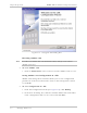
LINK (green) ON – Good Ethernet link integrity Rear panel LAN
connector
ACT (yellow) Blinks according to the Ethernet traffic Rear panel LAN
connector
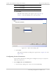
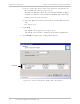
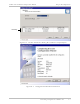
4.2 Operating AirMux-200
Turning On AirMux-200
ä
To turn on AirMux-200:
• Connect the AC/DC converter to the IDU power connector and to
the mains.
The PWR indicator lights up and remains lit as long as the IDU is
receiving power.
AirMux-200 requires no operator attention once installed, with the
exception of occasional monitoring of front panel indicators and
statistics data. Intervention is only required when AirMux-200 must be
configured to its operational requirements, or diagnostic tests are
performed.
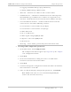
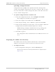
Normal Indications
Upon turning on AirMux-200, the PWR LED in the IDU front panel lights
to indicate that AirMux-200 is on. Table 4-2 shows the correct status
of the indicators a few seconds after power-up.
Table 4-2. AirMux-200 Indicator Status
Indicator Status
PWR ON
RTCB Green – Blinking
slowly
RT Green – Blinking
slowly
Air Green – Blinking
slowly
Service Green – Blinking
slowly