
User Manual

Front Panel Indicators 4-1
Chapter 4
Operation
This chapter provides the following information for AirMux-200:
• AirMux-200 front panel indicators
• Operating procedures (turn-on, front panel indications,
performance monitoring and turn-off)
• Procedures for changing AirMux-200 configuration parameters.
4.1 Front Panel Indicators
The front panel of AirMux-200 includes a series of LED indicators that
show the current operating status of the unit.
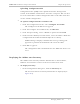
Figure 4-1 shows the front panel of the AirMux-200 unit. Table 4-1
describes the AirMux-IDU indicators.
AirMux-IDU
SERVICE
AIR I/F
RTCB
RT
PWR
Figure 4-1. Front Panel
Table 4-1. IDU LEDs
Name Function Location
SERVICE
(green/red)
ON (green) – E1 or T1 line is synchronized
ON (red) – Alarm is detected at the E1 or T1 interface
Front panel
AIR I/F (red) ON (green) – Wireless link is synchronized
ON (red) – Wireless link lost synchronization
Front panel
RTCB (green) ON – IDU self-test was completed successfully Front panel
RT
(green/red)
ON (green) – ODU-to-IDU communication link is operating
properly
ON (red) – ODU-to-IDU communication link is disrupted
Front panel
PWR (green) ON – A power supply is ON Front panel