
User Manual

Chapter 1 Introduction AirMux-200 Installation and Operation Manual
1-4 Physical Description
1.2 Physical Description
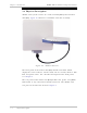
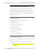
AirMux-200 system consists of a radio terminal (ODU) and an indoor
unit (IDU). Figure 1-2 illustrates an AirMux-200 unit assembly.
Figure 1-2. AirMux-200 Unit
The front panel of the indoor unit (IDU) includes five LEDs, which
display the status of E1/T1, wireless link, self-test results, ODU-to-IDU
link, and power status. For a detailed description of the front panel,
see Chapter 4.
The rear panel of the indoor unit (IDU) includes the power, user (WAN,
LAN and E1 or T1), and radio terminal connectors. The AirMux-200
rear panel is described in detail in Chapter 3.