
Installation Guide
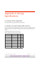
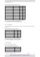

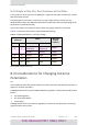
Table Of Contents
- Installation Guide
- Table of Contents
- Chapter 1: Introduction
- Chapter 2: Installation Steps
- 2.1 Prepare Laptop
- 2.2 Connect Laptop to Radio Unit
- 2.3 Update Connectivity Parameters of Radio Unit
- 2.4 Check items to be installed
- 2.5 Prepare Tools
- 2.6 Mount the HBS
- 2.7 Connect HBS antenna
- 2.8 Install SU Mounting Kit
- 2.9 Mounting the SU
- 2.10 Ground Radio Unit
- 2.11 Mounting the Lightning Protection Units
- 2.12 Waterproofing
- 2.13 Connect Radio (External Connections)
- 2.14 Check Connectivity to Radio
- 2.15 Request (and receive) permitted frequencies
- 2.16 Activate HBS
- 2.17 Align SU Unit
- Chapter 3: Safety Practices and Provisions
- Appendix A: Wiring Specifications
- Appendix B: About Antennas
- Appendix C: Terminology
- Appendix D: Certified Antennas
- RADWIN Worldwide Offices

TVWhiteSpaceInstallationGuide Release1.0 A‐2
ScopeofthisAppendix
A.2UserPortConnectors
A.2.1LANPort
TheLAN10/100BaseTinterfaceterminatesinan8‐pinRJ‐45connector,wiredinaccordance
toTable A‐3.
A.3DCPowerTerminals
A.3.1DCPoE
DCpowerterminalsareasfollows:
TableA‐2:LAN‐GbEPoERJ‐45ConnectorPinout
Function Color PoE LAN
TxRxA White/Green 1 1
TxRxA Green 2 2
TxRxB White/Orange 3 3
TxRxB Orange 6 6
TxRxC&Power(+) Blue 4 4
TxRxC&Power(+) White/Blue 5 5
TxRxD&Power(‐) White/Brown 7 7
TxRxD&Power(‐) Brown 8 8
TableA‐3:FastEthernetConnectorPinout
Function Signal Pin
TransmitData(positive) TD(+) 1
TransmitData(negative) TD(–) 2
ReceiveData(positive) RD(+) 3
ReceiveData(negative) RD(–) 6
TableA‐4:TerminalBlock2‐pin‐48VDC
Function Pin
+ Right
– Left
FOR REGULATORY USES ONLY