
User manual
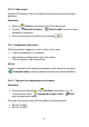
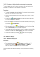
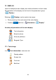
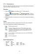
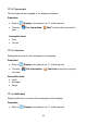
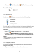
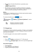
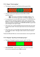
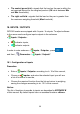
Table Of Contents
- 1. INTENDED USE
- 2. PRECAUTIONARY MEASURES
- 3. WARRANTY CONDITIONS
- 4. UNPACKING AND MOUNTING
- 5. CONSTRUCTION
- 6. GETTING STARTED
- 7. KEYPAD OVERLAY
- 8. FUNCTIONS OF KEYS
- 9. PROGRAM STRUCTURE
- 10. INDICATING WINDOW
- 11. LOGGING ON
- 12. NAVIGATING WITHIN THE MENU
- 13. WEIGHING
- 14. SCALE PARAMETERS
- 15. COMMUNICATION
- 16. DEVICES
- 17. DISPLAY
- 18. INPUTS / OUTPUTS
- 19. AUTHORIZATION
- 20. OTHER PARAMETERS
- 21. CUSTOMER CALIBRATION
- 22. SPECIAL FUNCTIONS OF WORKING MODES
- 23. WORK MODE - WEIGHING
- 24. WORKING MODES – COUNTING PIECES
- 25. WORKING MODES – DEVIATIONS
- 26. WORKING MODES – COMPARATOR
- 27. DATABASES
- 28. COMMUNICATION PROTOCOL
- 28.1. General information
- 28.2. Inventory of RS commands
- 28.3. Respond message format
- 28.4. Command’s description
- 28.4.1. Zeroing
- 28.4.2. Tarring
- 28.4.3. Get tare value
- 28.4.4. Set tare value
- 28.4.5. Send the stable result in basic unit
- 28.4.6. Send the result immediately in basic unit
- 28.4.7. Send the stable result in current unit
- 28.4.8. Send the result immediately in current unit
- 28.4.9. Switch on continuous transmission in basic unit
- 28.4.10. Switch off continuous transmission in basic unit
- 28.4.11. Switch on continuous transmission in current unit
- 28.4.12. Switch off continuous transmission in current unit
- 28.4.13. Set lower threshold
- 28.4.14. Set upper threshold
- 28.4.15. Read lower threshold
- 28.4.16. Read upper threshold
- 28.4.17. Send all implemented commands
- 28.5. Manual printouts / automatic printouts
- 29. CONNECTING EXTERNAL DEVICES
- 30. DIAGRAMS OF CONNECTION CABLES
- 31. TECHNICAL PARAMETERS
- 32. ERROR MESSAGES
- 33. ADDITIONAL EQUIPMENT
- 34. APPENDIX A – Variables for printouts
- 35. APPENDIX B – Functions of programmable buttons
- 36. APPENDIX C – Label pattern
- 37. APPENDIX D - CITIZEN printer setting
- 38. APPENDIX E - ZEBRA printer setting
- 39. APPENDIX F - Communication with barcode scanners
17.4.1. Bargraf “Quick weighing”
• The bargraph consists of 8 red fields and three green fields.
• The green fields signal weighings between MIN and MAX
threshold, where:
MIN = the minimum threshold of acceptable weighing - LO
MAX = the maximum threshold of acceptable weighing - HI
• If a measurement is over the MIN (to the value of 1/3 of MIN-MAX) the
green field with a triangle on the left is visible. If the measurement is
between 1/3 and 2/3 of MIN-MAX the rectangular green field is visible.
If the measurement is between 2/3 of MIN-MAX and MAX a green field
with a triangle on the right is visible.
• If the mass value is below the MIN threshold red fields with red arrows
on the left are visible. The lower mass value the more red arrows are
visible.
• If the mass value is over the MAX threshold red fields with red arrows
on the right are visible. The higher mass value the more red arrows
are visible.
Thresholds MIN and MAX are on the borders between red and green fields.
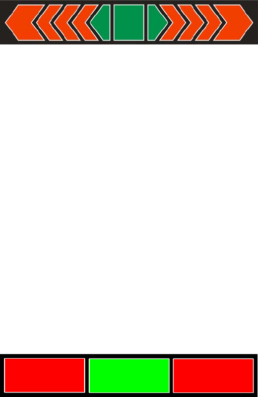
17.4.2. Bargraph “Signalling checkweighing ranges”
• This type of bargraph comprises one green and 2 red fields.
• The left red field – signals that the load on the pan is lower than
the minimum weighing threshold (Min threshold);
49