
User manual
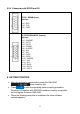
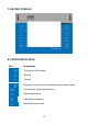
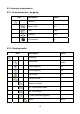
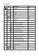
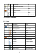
Table Of Contents
- 1. INTENDED USE
- 2. PRECAUTIONARY MEASURES
- 3. WARRANTY CONDITIONS
- 4. UNPACKING AND MOUNTING
- 5. CONSTRUCTION
- 6. GETTING STARTED
- 7. KEYPAD OVERLAY
- 8. FUNCTIONS OF KEYS
- 9. PROGRAM STRUCTURE
- 10. INDICATING WINDOW
- 11. LOGGING ON
- 12. NAVIGATING WITHIN THE MENU
- 13. WEIGHING
- 14. SCALE PARAMETERS
- 15. COMMUNICATION
- 16. DEVICES
- 17. DISPLAY
- 18. INPUTS / OUTPUTS
- 19. AUTHORIZATION
- 20. OTHER PARAMETERS
- 21. CUSTOMER CALIBRATION
- 22. SPECIAL FUNCTIONS OF WORKING MODES
- 23. WORK MODE - WEIGHING
- 24. WORKING MODES – COUNTING PIECES
- 25. WORKING MODES – DEVIATIONS
- 26. WORKING MODES – COMPARATOR
- 27. DATABASES
- 28. COMMUNICATION PROTOCOL
- 28.1. General information
- 28.2. Inventory of RS commands
- 28.3. Respond message format
- 28.4. Command’s description
- 28.4.1. Zeroing
- 28.4.2. Tarring
- 28.4.3. Get tare value
- 28.4.4. Set tare value
- 28.4.5. Send the stable result in basic unit
- 28.4.6. Send the result immediately in basic unit
- 28.4.7. Send the stable result in current unit
- 28.4.8. Send the result immediately in current unit
- 28.4.9. Switch on continuous transmission in basic unit
- 28.4.10. Switch off continuous transmission in basic unit
- 28.4.11. Switch on continuous transmission in current unit
- 28.4.12. Switch off continuous transmission in current unit
- 28.4.13. Set lower threshold
- 28.4.14. Set upper threshold
- 28.4.15. Read lower threshold
- 28.4.16. Read upper threshold
- 28.4.17. Send all implemented commands
- 28.5. Manual printouts / automatic printouts
- 29. CONNECTING EXTERNAL DEVICES
- 30. DIAGRAMS OF CONNECTION CABLES
- 31. TECHNICAL PARAMETERS
- 32. ERROR MESSAGES
- 33. ADDITIONAL EQUIPMENT
- 34. APPENDIX A – Variables for printouts
- 35. APPENDIX B – Functions of programmable buttons
- 36. APPENDIX C – Label pattern
- 37. APPENDIX D - CITIZEN printer setting
- 38. APPENDIX E - ZEBRA printer setting
- 39. APPENDIX F - Communication with barcode scanners
5.2.4. Connector with RS232 and I/O
RS232 - DB9/M (male),
top view:
Pin2 - RxD
Pin3 - TxD
Pin5 - GND
I/O, RS232 DSUB15/F (female),
top view:
Pin1 - GNDWE
Pin2 - OUT1
Pin3 - OUT2
Pin4 - COMM
Pin5 - 6÷9VDC
Pin6 - IN4
Pin7 - IN3
Pin8 - TxD2
Pin9 - 5VDC
Pin10 - GNDRS
Pin11 - IN2
Pin12 - IN1
Pin13 - RxD2
Pin14 - OUT4
Pin15 - OUT3
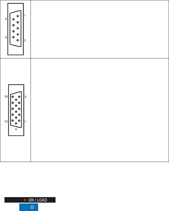
6. GETTING STARTED
• After the terminal is connected to power the ON/LOAD
diode starts to light.
• Press
to start the operating system loading procedure.
Windows CE together with RADWAG software loading is signalled
by blinking the red diode ON/LOAD.
• When the loading procedure is completed the main software
window appears.
11