
Installation guide

•
If the included video cables cannot be used for your system because of length
requirements, ensure you have a video cable with 1080p60 support
Procedure
Step 1
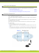
Remove the camera stabilizing cartons.
Caution
Always remove the camera stabilizing cartons before connecting the camera.
Caution
Do not place the camera on top of the XT Codec Unit. It can cause the system
to overheat.
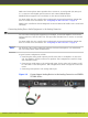
Step 2
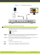
Connect the camera to the DVI Input connector on the XT Codec Unit:
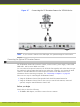
Figure 4-8 Connecting the optional XT Premium Camera for SCOPIA XT5000
Series
Note
If you connect a camera to the DVI-I input, the system manages it as PC content.
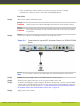
Step 3
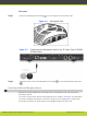
Connect the power supply cable to the DC IN connector on the camera.
Step 4
Plug the power supply cable into one of the power sockets on the wall.
Step 5
To enable controlling the camera using the XT Remote Control Unit, connect a crossed VISCA
control cable to the RS-232C IN connector on the camera and to the RS-232C OUT connector
on the main camera. For instructions, see “Connecting Cameras for Controlling the Optional
XT Premium Camera with the XT Remote Control Unit” on page 33.
Step 6
Apply power to the camera.
RADVISION | Installation Guide for SCOPIA XT5000 Series Version 3.1 Setting up the SCOPIA XT Series | 32