
Installation guide
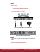
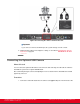
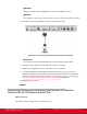


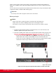
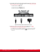


Table Of Contents
- Installation Guide for Scopia XT5000 Endpoint with Embedded Server for IP Office Version 3.2
- Table of Contents
- Chapter 1: About the Scopia XT Endpoint for IP Office
- Chapter 2: Installation Workflow for Scopia XT Endpoint for IP Office
- Chapter 3: Planning the Topology of the Scopia XT Endpoint for IP Office Deployment
- About the Scopia XT Endpoint for IP Office Embedded MCU
- Planning the Topology of Scopia XT Endpoint for IP Office with Scopia XT Desktop
- Planning NAT and Firewall Traversal with Scopia XT Endpoint for IP Office
- Supporting ISDN Connectivity
- Implementing External API Control
- Implementing Port Security for the Scopia XT Endpoint for IP Office
- Chapter 4: Prerequisites for Setting up the System
- Chapter 5: Setting up the Scopia XT Endpoint for IP Office
- Mounting the XT Codec Unit
- Connecting Scopia XT Endpoint for IP Office to Your Network
- Connecting a Computer to the Scopia XT Endpoint for IP Office
- Selecting the Computer Display Resolution
- Connecting Audio Equipment to the Scopia XT Endpoint for IP Office
- Connecting the Video Equipment to the Scopia XT Endpoint for IP Office
- Connecting the Primary XT Premium Camera
- Connecting the Optional USB Camera
- Connecting the Optional XT Premium Camera
- Connecting Cameras for Controlling the Optional XT Premium Camera with the XT Remote Control Unit
- Connecting the Optional Scopia XT Camera Switch
- Connecting a DVD or Blu-ray Player
- Connecting Analog Video Equipment
- Installing the Batteries of the XT Remote Control Unit
- Chapter 6: Initial Configuration
- How to Control the XT Endpoint
- Registering and Enabling your Scopia XT Endpoint for IP Office license
- Performing Basic Configuration
- Registering the XT Endpoint to IP Office
- Setting Basic System Information
- Configuring Video Connections
- Configuring Audio Connections
- Configuring Network Settings
- Chapter 7: Securing your Scopia XT Endpoint for IP Office
- Chapter 8: Troubleshooting the Scopia XT Endpoint for IP Office
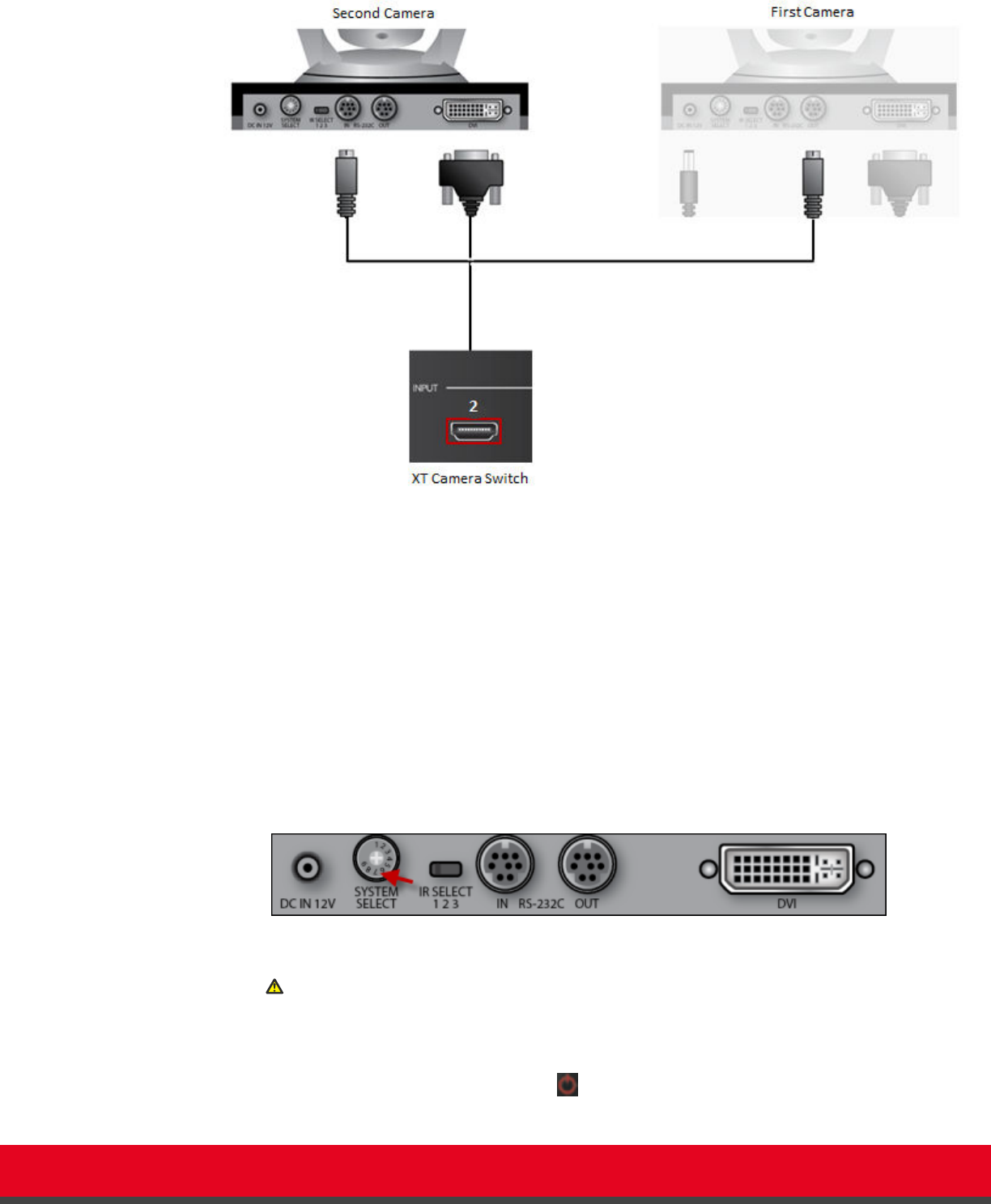
Figure 28: Connecting the second camera
•
Attach one end of the VISCA control cable to the IN RS-232C connector on the
second camera.
•
Attach the other end to the OUT RS-232C connector on the first camera.
b. Connect the DVI-HDMI cable:
•
Attach the DVI connector to the DVI socket on the second camera.
•
Attach the HDMI connector to the HDMI socket labeled 2 on the Scopia XT
Camera Switch.
6. If required, repeat the above step for a third or fourth camera.
7. Check that the SYSTEM SELECT switch on the back panel of each camera is set to 7:
Figure 29: Checking the SYSTEM SELECT switch
Caution:
To adjust the switch, you must first turn the camera off. Adjust it using a slotted 2.5 mm
screwdriver.
8.
Turn on the XT Codec Unit by pressing the power key on the XT Remote Control Unit.
This also turns on the Scopia XT Camera Switch.
Installation Guide for Scopia XT5000 Endpoint with Embedded
Server for IP Office Version 3.2
Setting up the Scopia XT Endpoint for IP Office | 50