
Installation guide
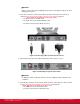
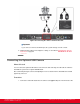


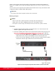
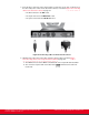


Table Of Contents
- Installation Guide for Scopia XT5000 Endpoint with Embedded Server for IP Office Version 3.2
- Table of Contents
- Chapter 1: About the Scopia XT Endpoint for IP Office
- Chapter 2: Installation Workflow for Scopia XT Endpoint for IP Office
- Chapter 3: Planning the Topology of the Scopia XT Endpoint for IP Office Deployment
- About the Scopia XT Endpoint for IP Office Embedded MCU
- Planning the Topology of Scopia XT Endpoint for IP Office with Scopia XT Desktop
- Planning NAT and Firewall Traversal with Scopia XT Endpoint for IP Office
- Supporting ISDN Connectivity
- Implementing External API Control
- Implementing Port Security for the Scopia XT Endpoint for IP Office
- Chapter 4: Prerequisites for Setting up the System
- Chapter 5: Setting up the Scopia XT Endpoint for IP Office
- Mounting the XT Codec Unit
- Connecting Scopia XT Endpoint for IP Office to Your Network
- Connecting a Computer to the Scopia XT Endpoint for IP Office
- Selecting the Computer Display Resolution
- Connecting Audio Equipment to the Scopia XT Endpoint for IP Office
- Connecting the Video Equipment to the Scopia XT Endpoint for IP Office
- Connecting the Primary XT Premium Camera
- Connecting the Optional USB Camera
- Connecting the Optional XT Premium Camera
- Connecting Cameras for Controlling the Optional XT Premium Camera with the XT Remote Control Unit
- Connecting the Optional Scopia XT Camera Switch
- Connecting a DVD or Blu-ray Player
- Connecting Analog Video Equipment
- Installing the Batteries of the XT Remote Control Unit
- Chapter 6: Initial Configuration
- How to Control the XT Endpoint
- Registering and Enabling your Scopia XT Endpoint for IP Office license
- Performing Basic Configuration
- Registering the XT Endpoint to IP Office
- Setting Basic System Information
- Configuring Video Connections
- Configuring Audio Connections
- Configuring Network Settings
- Chapter 7: Securing your Scopia XT Endpoint for IP Office
- Chapter 8: Troubleshooting the Scopia XT Endpoint for IP Office
3. Insert the three connectors of the camera cable (3 connectors on one side, 2 connectors on
the other side) to the sockets on the back of the camera, as shown in Figure 18: Connecting
cables to the back of the camera on page 41:
•
The DVI connector to the DVI socket
•
The 8-pin connector to the IN RS232C socket
•
The power connector to the DC IN 12V socket
Figure 26: Connecting cables to the back of the camera
4. Attach the two connectors on the other end of the camera cable as shown in Figure
27: Connecting cables to the Scopia XT Camera Switch on page 49:
a. The HDMI connector to the HDMI socket labeled 1 on the Scopia XT Camera Switch.
b.
The connector for power and serial control to the horizontal socket on the XT
Codec Unit.
Installation Guide for Scopia XT5000 Endpoint with Embedded
Server for IP Office Version 3.2
Setting up the Scopia XT Endpoint for IP Office | 48