
Installation guide
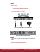
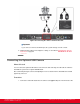
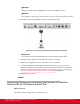


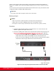
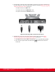


Table Of Contents
- Installation Guide for Scopia XT5000 Endpoint with Embedded Server for IP Office Version 3.2
- Table of Contents
- Chapter 1: About the Scopia XT Endpoint for IP Office
- Chapter 2: Installation Workflow for Scopia XT Endpoint for IP Office
- Chapter 3: Planning the Topology of the Scopia XT Endpoint for IP Office Deployment
- About the Scopia XT Endpoint for IP Office Embedded MCU
- Planning the Topology of Scopia XT Endpoint for IP Office with Scopia XT Desktop
- Planning NAT and Firewall Traversal with Scopia XT Endpoint for IP Office
- Supporting ISDN Connectivity
- Implementing External API Control
- Implementing Port Security for the Scopia XT Endpoint for IP Office
- Chapter 4: Prerequisites for Setting up the System
- Chapter 5: Setting up the Scopia XT Endpoint for IP Office
- Mounting the XT Codec Unit
- Connecting Scopia XT Endpoint for IP Office to Your Network
- Connecting a Computer to the Scopia XT Endpoint for IP Office
- Selecting the Computer Display Resolution
- Connecting Audio Equipment to the Scopia XT Endpoint for IP Office
- Connecting the Video Equipment to the Scopia XT Endpoint for IP Office
- Connecting the Primary XT Premium Camera
- Connecting the Optional USB Camera
- Connecting the Optional XT Premium Camera
- Connecting Cameras for Controlling the Optional XT Premium Camera with the XT Remote Control Unit
- Connecting the Optional Scopia XT Camera Switch
- Connecting a DVD or Blu-ray Player
- Connecting Analog Video Equipment
- Installing the Batteries of the XT Remote Control Unit
- Chapter 6: Initial Configuration
- How to Control the XT Endpoint
- Registering and Enabling your Scopia XT Endpoint for IP Office license
- Performing Basic Configuration
- Registering the XT Endpoint to IP Office
- Setting Basic System Information
- Configuring Video Connections
- Configuring Audio Connections
- Configuring Network Settings
- Chapter 7: Securing your Scopia XT Endpoint for IP Office
- Chapter 8: Troubleshooting the Scopia XT Endpoint for IP Office

You can control the optional camera using the XT Remote Control Unit instead of the camera remote
control. To do this, you must connect a VISCA Cross cable between the main and the optional cameras.
Important:
The camera remote control is disabled when you connect the main and optional cameras using a
VISCA Cross cable.
VISCA Control is a standard protocol to control PTZ Cameras. VISCA Control is implemented through
the cable connection from the main camera to the CTRL CAM input of the XT Codec Unit. Through the
VISCA interface, the XT Codec Unit sends commands that change the camera capture resolution, PTZ
properties and more.
You can control and include more than one HDMI camera in your video by connecting them to the
Scopia XT Camera Switch (purchased separately). Multiple cameras are typically used for larger
meeting rooms or auditoriums. For example, you may want to zoom one camera to focus on the
speaker, and use another camera for the audience. Connecting the Scopia XT Camera Switch also
allows you use multiple cameras while still keeping the DVI port open to connect a computer and share
content. For more information about connecting the Scopia XT Camera Switch, see Connecting the
Optional Scopia XT Camera Switch on page 46.
Before you begin
•
Buy a VISCA Cross cable, available in the optional cable kit. Alternatively, you can create a cable
of the required length if you’re planning to position the optional camera far away from the XT
Codec Unit.
•
If the XT Codec Unit is installed in a cabinet, the XT Codec Unit IR receiver cannot function
properly. In this case, the IR sensor of the main camera (not the optional camera) receives the IR
signals coming from the XT Remote Control Unit and sends them to the XT Codec Unit through the
VISCA interface.
For this type of setup, enable the Always power on camera field in Administrator settings > I/O
Inputs > Cameras (for details, see
Configuring the Camera Connection on page 95).
Procedure
1. Measure the distance that separates the main camera from the optional camera, and cut the
cable to the required length. The cable’s maximal allowed length is 15m (50ft). Attach each
end of the VISCA Cross cable to an 8-pin mini-DIN male connector.
Installation Guide for Scopia XT5000 Endpoint with Embedded
Server for IP Office Version 3.2
Setting up the Scopia XT Endpoint for IP Office | 45