
Installation guide
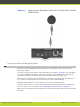
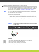
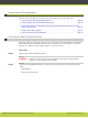
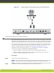
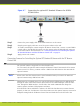
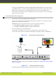
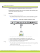

Figure 4-7 Connecting the optional XT Standard II Camera for SCOPIA
XT5000 Series
Step 3
Connect the power supply cable to the DC IN connector on the camera.
Step 4
Plug the power supply cable into one of the power sockets on the wall.
Step 5
To enable controlling the camera using the XT Remote Control Unit, connect a crossed VISCA
control cable to the RS-232C IN connector on the camera and to the RS-232C OUT connector
on the main camera. For instructions, see “Connecting Cameras for Controlling the Optional
XT Standard II Camera with the XT Remote Control Unit” on page 21.
Step 6
Apply power to the camera.
Connecting Cameras for Controlling the Optional XT Standard II Camera with the XT Remote
Control Unit
The optional camera is supported for selected models only.
You can control the optional camera using the XT Remote Control Unit instead of the camera
remote control. To do this, you must connect a VISCA Cross cable between the main and the
optional cameras.
Note
Please notice that the camera remote control is disabled when you connect the main and
optional cameras using a VISCA Cross cable.
VISCA Control is a standard protocol to control PTZ Cameras. VISCA Control is implemented
through the cable connection from the main camera to the CTRL CAM input of the XT Codec
Unit. Through the VISCA interface, the XT Codec Unit sends commands that change the
camera capture resolution, PTZ properties and more.
If the XT Codec Unit is installed in a cabinet, the XT Codec Unit IR receiver cannot function
properly. In this case, the IR sensor of the main camera (not the optional camera) receives the
IR signals coming from the XT Remote Control Unit and sends them to the XT Codec Unit
RADVISION | Installation Guide for SCOPIA XT4000 Series Version 3.0 Setting up the SCOPIA XT Series | 21