SCOPIA XT4000 Series Installation Guide Version 3.
© 2000-2012 RADVISION Ltd. All intellectual property rights in this publication are owned by RADVISION Ltd and are protected by United States copyright laws, other applicable copyright laws and international treaty provisions. RADVISION Ltd retains all rights not expressly granted. All product and company names herein may be trademarks of their registered owners. This publication is RADVISION confidential.
Table of Contents 1 About the SCOPIA XT Series 2 Planning the Topology of the SCOPIA XT Series Deployment Using SCOPIA XT Series as Endpoints.................................................................. 4 Planning NAT and Firewall Traversal with SCOPIA XT Series....................................... 5 Supporting ISDN Connectivity.......................................................................... 9 Implementing External API Control.............................................................
Connecting Analog Stereo Audio Equipment to the Analog Connector.................... 18 Connecting the Video Equipment.................................................................... 19 Connecting the Main XT Standard II Camera.................................................. 19 Connecting the Optional XT Standard II Camera..............................................20 Connecting Cameras for Controlling the Optional XT Standard II Camera with the XT Remote Control Unit................................
Configuring Audio Outputs.......................................................................53 Configuring Network Settings......................................................................... 55 Configuring GLAN Use............................................................................ 55 Configuring IP Addresses................................................................... 56 Configuring Network Connectivity........................................................
1 About the SCOPIA XT Series The SCOPIA XT Series incorporates the latest state-of-the-art video technology for room high definition (HD) conferencing, including support for dual stream HD video, high quality data sharing, high quality full band audio and a high capacity embedded MCU (selected models).
The SCOPIA XT4000 Series provides cost-effective true HD 720p videoconferencing at 60 fps with the impressive price performance. It is a new innovative small room series, incorporating dual 720p at 60 fps live video and content, high profile H.264 and scalable video coding technology (SVC). Furthermore, the SCOPIA XT4000 Series guarantees 20 kHz full band audio with 48 kHz sampling rate, ensuring high clarity audio transmission with no loss of quality.
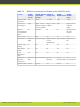
Table 1-1 Differences in features for models in the SCOPIA XT Series Feature SCOPIA XT1000 Piccolo SCOPIA XT1000 SCOPIA XT and SCOPIA Telepresence XT1200 SCOPIA SCOPIA XT4000 Series XT5000 Series Maximum HD resolution 720p 1080p 720p 1080p Frames Per Second (fps) 30fps 30fps, 720p at 30fps, or 720p 60fps (incoming at 60fps only on XT1000) 60fps 60fps, both at 720p and 1080p Hosting No videoconferenc es (embedded MCU) Optional No No Optional (from the next version) Optical zoom 5x 10x
2 Planning the Topology of the SCOPIA XT Series Deployment There are a number of ways that the SCOPIA XT Series can be deployed in a network, depending on its use as a room system endpoint, a conference hosting system, and the nature of the endpoints connecting to the unit. • Using SCOPIA XT Series as Endpoints ...................................................... • Planning NAT and Firewall Traversal with SCOPIA XT Series ........................... • Supporting ISDN Connectivity ......................
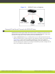
Figure 2-1 SCOPIA XT Series as Endpoints Planning NAT and Firewall Traversal with SCOPIA XT Series SCOPIA XT Series fully supports NAT and firewall traversal, enabling you to place the unit behind a NAT router or firewall and connect with other endpoints seamlessly.
Figure 2-2 Using an HTTP/STUN Server for NAT and Firewall Traversal This approach works well in simple NAT and firewall traversal deployments, typically used by home offices and Small Medium Businesses (SMBs). • Using a NAT/firewall traversal server supporting H.460 The endpoints in the private network communicate with the endpoints located in the public network via an H.460 NAT/firewall traversal server, like the SCOPIA PathFinder (see Figure 2-3 on page 7).
Figure 2-3 Using a NAT and Firewall Traversal Server Configure the traversal server as the XT Codec Unit gatekeeper and enable the H.460 option. Configure the XT Codec Unit to the IP address of the traversal server SCOPIA PathFinder. • Using the XT Series for NAT and firewall traversal In cases where your organization has no sophisticated firewall protection, the XT Series can straddle the two network zones using the two network ports provided on the XT Codec Unit (see Figure 2-4 on page 8).
Figure 2-4 Using XT Series for NAT and Firewall Traversal There are two possible setups in the GLAN1 and GLAN2 configuration (see Figure 2-4 on page 8): 1. When there is no gatekeeper, XT Series communicates simultaneously with the public and private network endpoints using IP addresses. This configuration is suitable for SMBs. 2. When there is a gatekeeper, it is configured to manage the private network endpoints.
Supporting ISDN Connectivity The SCOPIA XT Series supports ISDN connectivity, allowing calls from endpoints to be routed to the relevant conference using the SCOPIA BRI (Basic Rate Interface) and PRI (Primary Rate Interface) gateways. RADVISION has implemented a special pairing mechanism between the gateway and the endpoint so that ISDN dialing is very simple. After pairing the systems, the participants place ISDN calls by dialing the remote party ISDN number.
3 Prerequisites for Setting up the System Before beginning the installation of the system, you must read the safety regulations for a safe use of the system, verify the conference room setup, and check that the product corresponds to your order. The setup prerequisites are described in these sections: • Complying with Safety Regulations ...................................................... • Planning the Conference Room Setup ................................................... • Inspecting the Product .
Place the camera(s) in a position to ensure eye contact between local and remote participants. Recommended position is either directly below or directly above the monitors, in central position, at a distance which enables capture of the entire table. Place the Microphone Pod at the center of the table. To help with echo cancellation, we recommend to position the Microphone Pod as far as possible from loudspeakers and other noise sources (for example, computer fans).
For a list of package contents see the invoice shipped with your order. Report any damage or missing items to your distributor or reseller. Keep the package and its contents for inspection resulting from loss or damage claim. RADVISION | Installation Guide for SCOPIA XT4000 Series Version 3.
4 Setting up the SCOPIA XT Series After reading the section “Prerequisites for Setting up the System” on page 10, you can install the SCOPIA XT Series. These sections describe how to install the XT Codec Unit and connect it to its peripherals: • Mounting of the XT Codec Unit ........................................................... • Connecting SCOPIA XT Series ............................................................. • Connecting SCOPIA XT Series to Your Network ...................................
Connecting SCOPIA XT Series For operational information about connecting SCOPIA XT5000 Series, refer to the Quick Setup Guide for SCOPIA XT5000 Series. Connecting SCOPIA XT Series to Your Network Your SCOPIA XT Series has two GLAN ports for connecting to the network. The second GLAN port is optional and can be enabled by using the license. For more information, refer to “Installing and Enabling Licenses which Extend System Functionality” on page 27.
Figure 4-2 Connecting the XT Codec Unit to a private and a public network with multiple routers in both networks Connecting the Audio Equipment These sections describe how to connect the audio peripherals to the XT Codec Unit. • Connecting the Microphone Pod .......................................................... • Connecting an External Microphone System ............................................ • Connecting Analog Stereo Audio Equipment to the Analog Connector ..............
Figure 4-3 Microphone Setup Procedure Connect the Microphone Pod output RADVISION | Installation Guide for SCOPIA XT4000 Series Version 3.0 to the rear panel of the XT Codec Unit.
Figure 4-4 Connecting the Microphone Pods to the XT Codec Unit of SCOPIA XT4000 Series Connecting an External Microphone System When the two-pod configuration is not sufficient for covering the room, use an external microphone system. You need to acquire audio mixers from third-parties (for example, Clear One). An audio mixer can connect multiple microphones, mix them, cancel the echo and generate a single audio stream that feeds into the audio inputs of your SCOPIA XT Series XT Codec Unit.
Connecting Analog Stereo Audio Equipment to the Analog Connector You can connect analog audio equipment to the stereo analog connector of the XT Codec Unit. You must enable the echo canceller when working with an external microphone system that does not contain echo cancellation. See “Configuring the Echo Canceller” on page 52. Note The XT Codec Unit’s analog audio input supports a balanced microphone or an unbalanced line. The analog audio output is unbalanced.
Connecting the Video Equipment These sections describe how to connect the video devices to the XT Codec Unit. • Connecting the Main XT Standard II Camera ............................................ page 19 • Connecting the Optional XT Standard II Camera ....................................... page 20 • Connecting Cameras for Controlling the Optional XT Standard II Camera with the XT Remote Control Unit .......................................................................
Figure 4-6 Connecting the XT Standard II Camera for XT5000 Series Connecting the Optional XT Standard II Camera The XT Standard II Camera kit contains a camera, remote control, power supply, 5-meter DVIHDVI cable, and 10-meter VISCA cross cable. The kit does not contain cables since the optional camera location and distance from the XT Codec Unit varies significantly across installations.
Figure 4-7 Connecting the optional XT Standard II Camera for SCOPIA XT5000 Series Step 3 Step 4 Step 5 Plug the power supply cable into one of the power sockets on the wall. Step 6 Apply power to the camera. Connect the power supply cable to the DC IN connector on the camera. To enable controlling the camera using the XT Remote Control Unit, connect a crossed VISCA control cable to the RS-232C IN connector on the camera and to the RS-232C OUT connector on the main camera.
through the VISCA interface. For this type of setup, enable the Always power on camera field in Administrator settings > I/O Inputs > Cameras. Procedure Step 1 Buy a VISCA Cross cable from a third party, or create a cable of the required length if you’re planning to position the optional camera far away from the XT Codec Unit Measure the distance that separates the main camera from the optional camera, and cut the cable to the required length. The cable’s maximal allowed length is 15m (50ft).
Be aware that SCOPIA XT Series supports HDCP (High-bandwidth Digital Content Protection). As an HDCP Licensee, you may not use a digitally protected content on a device that copies HDCP content and you may not send digitally protected content to non-HDCP devices. If the XT Codec Unit detects that non-compliant devices are attached to one of the HD CAM inputs, the video is locked. Connecting Analog Video Equipment The XT Codec Unit features digital inputs and outputs.
Connecting the Computer You need a computer to share a presentation during a call. This procedure describes how to connect computers that are equipped with a DVI out or VGA out connector. The XT Codec Unit supports these DVI input formats: 1920 x 1080, 1440 x 900 (WSXGA), 1600 x 900 (HD+900p)1280 x 1024 (SXGA), 1280 x 720, 1280 x 768 (WXGA), 1280 x 960 (UVGA),1024 x 768 (XGA), 800 x 600 (SVGA), 640 x 480 (VGA).
Installing the Batteries of the XT Remote Control Unit When the XT Remote Control Unit's battery power is low, an icon appears on the GUI letting you know that you should replace the battery: • • Note Half-charged Battery Low Battery When the Low Battery icon appears on the display, we recommend to change batteries immediately, to ensure proper functioning of the system. For battery disposal information refer to the Safety Instructions leaflet.
5 Initial Configuration After connecting the system and powering it, perform the initial configuration as described in these sections: • Registering the SCOPIA XT Series to Obtain a License Key ............................ • Installing and Enabling Licenses which Extend System Functionality ................ • Enabling Remote Upgrade for Your SCOPIA XT Series .................................. • Performing Basic Configuration ...........................................................
You can find the user code (and the serial number) by selecting Configure > About from the Main menu. Step 3 Step 4 On a computer, open a browser and navigate to http://www.radvision.com/XT5000. Complete the online registration form and enter the serial number (or the user code) AND the product key. The web registration form returns a license key. Step 5 Step 6 Write down the license key and keep it in a safe place for future use. Use the license key to enable the software.
Procedure Step 1 Open the envelope that you obtained when you bought your license extension, or refer to the email you received after purchasing the license. Step 2 Locate the option key in the letter. Locate the serial number on the XT Codec Unit or the user code you received with the purchase. You can also retrieve the user code and serial number by selecting Configure > About from the Main menu. Step 3 Step 4 Step 5 Step 6 On a computer, open a browser and navigate to http://www.radvision.
Figure 5-1 Step 3 Enabling remote access to the SCOPIA XT Series Set the fields as required. Table 5-2 Enabling remote upgrade Field Name Description Download management Enables/disables downloading of firmware or patches to the XT Codec Unit. Step 4 Enable all addresses If set to Yes, enables access to the XT Codec Unit from any IP address in a network. If set to No, configure Address and SubNet mask. Address Enter the IP address allowed to access the XT Codec Unit.
• Adjusting the Image Position .............................................................. • Configuring Network Settings ............................................................. • Configuring Gatekeeper Settings ......................................................... page 31 page 33 page 33 The tasks appear in this section in the order they are presented in the quick setup wizard. The quick setup wizard automatically appears when you turn the XT Codec Unit on for the first time.
Figure 5-2 Step 2 Setting Country and Language Select the required country from the Country list using the arrow keys and press . The system menu and the Language field automatically change to the language used in the selected country. Step 3 If you want to change the language of the system menus, select the required language from the the Language list and press . The list of languages is displayed. Scroll to the preferred language and press . Step 4 Select Next to continue the basic configuration.
Figure 5-3 Step 2 Press 1 to align the top left corner. Figure 5-4 Step 3 Step 4 Step 5 Step 6 Examining the image position Adjusting the image position Use the arrow keys on the XT Remote Control Unit to position the image, and then press OK. Press 2 to align the bottom right corner. Use the arrow keys on the XT Remote Control Unit to position the image, and then press OK. Select Next. RADVISION | Installation Guide for SCOPIA XT4000 Series Version 3.
Configuring Network Settings This page allows you to setup the GLAN1 settings and the IP address the system uses for placing a call. Consult with your network administrator to configure these fields. Before you begin This procedure is performed as part of the basic configuration after “Adjusting the Image Position” on page 31. Procedure Step 1 Press and scroll to Yes from the Automatic IP address list. Figure 5-5 Step 2 Step 3 Defining IP Settings Configure the IP addresses.
Before you begin This procedure is performed as part of the basic configuration after “Configuring Network Settings” on page 33. Procedure Step 1 Set the Enabled list to Yes. Figure 5-6 Step 2 Step 3 Step 4 Step 5 XT Codec Unit Set the Mode list to Manual. Enter the IP address of the gatekeeper in the IP address field. Enter the H.323 number required to dial the XT Codec Unit in the Number H.323 field. Select Done. The basic configuration of your SCOPIA XT Series is complete.
Step 2 Step 3 Step 4 Select the Administrator Settings tab. Select Utilities in the left pane. Select Administrator or User under Password. Figure 5-7 Step 5 Step 6 Step 7 The Utilities page When setting up the user password, enable password use. Enter the old password, new password, and confirm the new password. Select Save.
Procedure Step 1 Step 2 Step 3 Access the SCOPIA XT Series web interface. In the Administrator Settings tab, select System > Date & Time > General on the left. Configure relevant settings as described in Table 5-3 on page 36. Table 5-3 Step 4 Step 5 Configuring the date and time settings Field Name Description Day Enter the date. Month Enter the month. Year Enter the year. Hour Enter the hour. Minutes Enter the minutes.
Table 5-4 Configuring time zone related settings Field Name Description Select the time zone to which the system belongs. Step 5 Step 6 Enable daylight time Set the daylight or summer time field to Yes or No according to the current daylight-saving status of your time zone. Start (dd/mm) Set the day and month to indicate when daylight saving times start. Stop (dd/mm) Set the day and month to indicate when daylight saving times end. Select Save. Press F5 to refresh the login.
Table 5-5 Step 5 Configuring regional information Field Name Description System name Enter the name that will appear in the local endpoint GUI and in the remote endpoint GUI (if connected). Country Select the country in which the local system is located. Once the country is selected, the other fields are populated automatically. Language Select the language used in the GUI. Audio coding Select the European or US coding.
Figure 5-8 Step 3 Step 4 Step 5 Setting the XT Remote Control Unit Code Enter the code in the Remote control code field. Select Save. On the XT Remote Control Unit, press and simultaneously. The On/Off key on the XT Remote Control Unit turns red. Step 6 Using the keypad, type the number you just entered in the Remote control code field. Note You must always use two digits for a code. For example, to set the code to “1”, enter “01”.
Figure 5-9 Step 3 Step 4 Step 5 Settings general user settings Select Yes from the Automatic screensaver list. Set the time after which the screen saver automatically starts on the display in the Minutes field. Select Save. Configuring Video Connections There are a number of settings which affect the way the camera accepts input and the way the monitors display video. • Configuring the Camera Connection ..................................................... • Configuring the Computer Connection ........
Figure 5-10 Step 3 Step 4 Configuring general camera settings Configure settings on the General page as described in Table 5-6 on page 41. Table 5-6 Configuring general camera settings Field Name Description Default camera Specifies to which input of the XT Codec Unit the main camera is connected. Typically it is HD CAM 1. The default camera is automatically activated when the system powers up. Driver Sets the camera driver for the connected camera.
Step 5 To configure the main camera connection: configure settings on the HD1 page as described in Table 5-7 on page 43, and then select Save. a. Select HD1 under Cameras. Figure 5-11 Configuring the main camera settings b. Configure the settings as described in Table 5-7 on page 43. RADVISION | Installation Guide for SCOPIA XT4000 Series Version 3.
Table 5-7 Configuring advanced camera settings Field Name Description Enable (this field Enable for the optional camera. appears on the HD2 and DVI pages only) Moving (PTZ) If necessary, enable the camera pan, tilt and zoom functionality. White balance mode In case the lighting in the room is not sufficient, you can make adjustments to the colors of the image sent by the camera. • To allow the camera to automatically adjusts colors to room lighting, set to Automatic.
Figure 5-12 Step 3 Step 4 Configuring the computer settings Select Yes from the Enable list to enable the DVI input. Select Save. Setting up the Monitor Display Modes The monitor can be configured from the SCOPIA XT Series by setting its resolution, and configuring the system to work with a single monitor or two monitors side-by-side. Some monitors crop the edges of the image shown in their displays. If this is the case, you need to adjust the way the image appears as described in this procedure.
• PaP (Picture and Picture) displays two images side-by-side on one monitor, where the remote image and the local image have the same size, emulating a dual-monitor setup. • PoP (Picture out Picture) displays two images side-by-side on one monitor, where the remote image is larger than the local image. Procedure Step 1 Step 2 Step 3 Step 4 Access the SCOPIA XT Series web interface. Select Administrator Settings. Select I/O connections. Select the General page under Monitor.
Table 5-8 Configuring general monitor settings Field Name Description Number of monitors Specifies the number of monitors connected to the XT Codec Unit. In a dual configuration, the selected layout is depicted as two pictures representing the two connected displays. • - The system automatically detects the number of connected monitors (recommended). • HD1/HD2 - When a single monitor is connected to the HD1/HD2 output socket of the XT Codec Unit.
Step 7 If necessary, adjust the way the image appears on the monitor: a. Select the monitor requiring adjustment (HD1 or HD2). b. Select Graphic adjustment under Monitor. c. Select your preferred image view mode • Menu • Menu and presentation (local and received). This is the default setting. • Menu, presentation, and live video. We do not recommend this setting as it might alter the proportions of the live images.
Table 5-9 Configuring PIP-PaP option Field Name Description Multi Image Mode Sets PIP and PaP activation, depending on the number of video streams available. Multi Image Type must be set to auto. • auto - PIP and PaP are enabled only when needed. This occurs when the number of video streams is greater than the number of available monitors. The order of the video streams is set automatically, with precedence to the remote video streams.
• Configuring Analog Audio Connections ................................................... • Configuring the Echo Canceller ........................................................... • Configuring Audio Outputs ................................................................ page 50 page 52 page 53 Configuring the Microphone Pod The Microphone Pod puts the focus on the speaker while isolating background noise. Procedure Step 1 Step 2 Step 3 Step 4 Access the SCOPIA XT Series web interface.
Table 5-10 Step 6 Configuring the Microphone Pod connection Field Name Description Enabled Enables/disables the Microphone Pod. Gain Use the slider to adjust the fixed Gain Control, setting the voice signal to the desired level. The AGC reduces the volume if the audio is strong and raises the volume if the audio is weak. Echo canceller Enable the echo canceller when working with an external microphone system that does not contain echo cancellation.
Field Name Description Enabled Enables/disables this audio input. Gain Set the voice signal to the desired level by using the slider. Echo canceller Enable the echo canceller when working with an external microphone system that does not contain echo cancellation. To configure the echo cancellation settings, see “Configuring the Echo Canceller” on page 52. To hear the audio also locally, see “Configuring Audio Outputs” on page 53.
Configuring the Echo Canceller If your SCOPIA XT Series works with an external microphone system that does not contain echo cancellation, perform this procedure to cancel echo. Before you begin Enable echo cancellation as described in “Configuring the Microphone Pod” on page 49. Procedure Step 1 Step 2 Step 3 Step 4 Access the SCOPIA XT Series web interface. Select Administrator Settings. Select I/O connections. Select Echo Canceller under to Audio - Input.
Table 5-11 Configuring echo canceller related settings Field Name Description AGC Enables/disables Automatic Gain Control. The AGC reduces the volume if the audio is strong and raises when it is weak. Noise reduction Enables/disables reduction of ambient noise in a conference room (e.g.: coughing, paper rustling, etc.). Audio delay automatic estimation An HDMI monitor might insert delay in the audio, causing an echo.
• If you are showing a presentation on your computer and it includes sound, route the sound of the computer to the analog input connector. Figure 5-18 Defining the routing of the audio outputs Procedure Step 1 Step 2 Access the SCOPIA XT Series web interface. In the Administrator settings tab, select I/O connections > Audio - Outputs > General. RADVISION | Installation Guide for SCOPIA XT4000 Series Version 3.
Step 3 Set the fields as required. Table 5-12 Configuring audio output settings Field Name Description Digital Audio to output If enabled, it routes the digital audio input port to one or more of the system’s audio output channels: HD1, digital audio and digital analog or all of the above. Echo Cancelled inputs to output If enabled, sends the echo cancelled input from the microphones to one of the system’s audio output channels: HD1, digital audio or analog output.
• Configuring IP Addresses ................................................................... • Configuring Network Connectivity ........................................................ • Enabling NAT and Firewall Traversal with SCOPIA XT Series .......................... • Configuring Dynamic Ports ................................................................ • Configuring Quality of Service (QoS) .....................................................
Step 8 Select Addresses under GLAN. Figure 5-20 Step 9 Configuring IP addresses Set the fields as described in Table 5-13 on page 57. Table 5-13 Configuring IP addresses Field Name Setting MAC address This setting cannot be changed. Automatic IP address Set to Yes (default) if the system gets its IP address automatically.
Configuring Network Connectivity If necessary you can configure the GLAN1 and GLAN2 ports. The GLAN2 port is available only if it is enabled. For more information, refer to “Installing and Enabling Licenses which Extend System Functionality” on page 27. Carefully match these settings with the equivalent settings in the network and the remote endpoints to avoid connectivity issues. Procedure Step 1 Step 2 Step 3 Step 4 Access the SCOPIA XT Series web interface. Select Administrator Settings.
Table 5-14 Configuring network connectivity Field Name Setting MTU Sets the maximum size of each IP packet the XT Codec Unit can send to the network. If the system or the remote endpoint transmits IP packets larger than the configured MTU size, they are dropped or fragmented. To avoid packet loss or fragmentation, decrease MTU. If packets are smaller than the configured MTU size, increase MTU.
Figure 5-22 Step 3 Configuring NAT traversal settings Set the fields as described in Table 5-15 on page 60. Table 5-15 Configuring NAT-related settings Field Name Description NAT Traversal Set to Yes to allow the system to be located behind a firewall/NAT. Set to No if the system is not located behind a firewall/NAT, but has a public IP address. NAT Discovery Manual method of setting the system’s firewall/NAT public IP address. Enter the Public IP address for that setting.
Configuring Dynamic Ports When a firewall is crossed, the firewall administrator must open a range of dynamic TCP and UDP ports to allow bidirectional IP traffic. Moreover, once the ports have been opened, the protocols [TCP 1720 (Q.931), TCP 1503 (T.120), UDP 1719, and 1718 (RAS)] involved in a call must be taken into account. Procedure Step 1 Step 2 Step 3 Step 4 Access the SCOPIA XT Series web interface. Select Administrator Settings. Select Networks. Select Dynamic ports under Preferences.
Step 6 Select Save. Configuring Quality of Service (QoS) Quality of Service determines how your network handles IP packets sent to your system during a video conference. Bandwidth and video quality settings also contribute to call quality. If you experience problems with call quality, refer to the Troubleshooting chapter of the Administrator Guide for SCOPIA XT Series. Before you begin Consult with your network administrator for more information about configuring Quality of Service.
Figure 5-24 Step 5 Configuring QoS settings Set the fields as described in Table 5-17 on page 63. Table 5-17 Configuring QoS settings Field Name Description Use QoS Enable/Disable QoS. If you set Use QoS to Yes, you will provide different priority to different data stream, or guarantee a certain level of performance to a data stream. In particular, you may choose between Precedence/TOS and Differentiated Service.
To do this, the gatekeeper must register all endpoints to maintain the mapping list of aliases and endpoints to successfully route calls. It also registers gateways to ensure that a call can be routed to a non-H.323 entity, since gateways form the bridge from H.323 to other protocols, such as ISDN. When registering with a gatekeeper like SCOPIA ECS Gatekeeper, the endpoint sends its IP and aliases.
Figure 5-26 Step 8 Configuring the Gatekeeper settings Set the fields as described in Table 5-19 on page 66. RADVISION | Installation Guide for SCOPIA XT4000 Series Version 3.
Table 5-19 Step 9 Configuring the gatekeeper Field Name Description Use gatekeeper Enables/disables the use of a gatekeeper. If No is selected, all the other fields are greyed. If Yes is selected, the XT Codec Unit can use the gatekeeper’s services. Automatic IP address Automatic gatekeeper discovery. The XT Codec Unit searches for an available gatekeeper. IP address Enter the IP address of the gatekeeper, if you do not use Automatic IP address. Use H.460 If set to Yes, the system uses H.
Configuring SIP Server Use The SCOPIA XT Series can be configured to function in a SIP environment, where aliases are managed by SIP servers rather than gatekeepers. In a SIP environment, a user can contact an endpoint by entering its alias, rather than having to remember the endpoint’s IP address. For example, you can dial “1234” or “joesmith” and the SIP server routes the call correctly.
Figure 5-27 Step 3 Configuring SIP settings Configure parameters as described in Table 5-20 on page 69. RADVISION | Installation Guide for SCOPIA XT4000 Series Version 3.
Table 5-20 Step 4 Configuring SIP-related parameters Parameter Description User Enter the system user name (alias). The system is registered to the SIP Registrar under this name. Authentication Name If necessary, enter the name for authenticating the XT Series with the SIP Proxy server and SIP Registrar. It can be the same as the User parameter. Authentication Password If necessary, enter the password for authenticating your XT Series with the SIP Proxy server and SIP Registrar.
other benefits like remote centralized upgrading and backing up of all endpoints in your video network. In deployments without iVIEW Management Suite, you can use the local built-in LDAP server that comes within every XT Series unit. LDAP servers are accessed using the H.350 protocol, which enhances the LDAP standard to include video endpoint information. Note When using SCOPIA iVIEW Management Suite, associate LDAP contacts to video endpoints otherwise these contacts are not displayed on the XT Series.
Figure 5-28 Configuring LDAP settings Step 3 Select Add Server. Step 4 Configure LDAP server settings as described in Table 5-21 on page 72. RADVISION | Installation Guide for SCOPIA XT4000 Series Version 3.
Table 5-21 Configuring LDAP server settings Field Name Description Type Allows to define the LDAP server. Address Indicates the LDAP server address. Port Indicates the port used to connect to the LDAP server. User The username and password with access to the information required in the remote LDAP server. The format of the username is in the form of a Distinguished Name (DN). The LDAP user of a XT Series is predefined, so when pointing to an XT Series this value cannot be edited.
Configuring Call Settings This procedure shows how to configure the system for support of incoming and outgoing calls. To configure the call settings remotely, access the SCOPIA XT Series web interface and navigate to Settings > Calls > Preferences > General and to Settings > Calls > Preferences > IP. Procedure Step 1 Step 2 Access the SCOPIA XT Series web interface. In the Administrator Settingstab, select Networks > Preferences > General.
Figure 5-30 Step 7 Configuring general call settings Set the fields as described in Table 5-23 on page 76. RADVISION | Installation Guide for SCOPIA XT4000 Series Version 3.
Step 8 Step 9 Step 10 Table 5-22 Configuring general call settings Field Name Description This is the default setting. It indicates that the system tries to choose the settings that best suit the local situation. Rate K (IP) Sets the maximum call rate that the system uses for all incoming or outgoing calls. Audio Coding (IP) Sets the preferred Audio Coding that the system tries to use for all incoming or outgoing calls, if the remote system supports the same Audio Coding.
Table 5-23 Step 11 Configuring the IP-related call settings Field Name Description DTMF RFC2833 (H.323) DTMF describes a method to send DTMF inside an audio stream. This method is normally used in SIP protocol but is uncommon in H.323. If set to Yes, the H.323 application in the XT Codec Unit can use DTMF transmission. Verify the remote endpoint supports RFC2833 before enabling this field.
Step 5 Step 6 Set the fields as required. Select Save. Configuring Video Compatibility with Older Systems Some older endpoint may be not fully compliant with more recent standard, and thus not able to recognize and manage recent video protocols. As a consequence, these endpoints may cause issues. The endpoint administrator must disable specific video codec if any compliance issue with older endpoints arises. Procedure Step 1 Step 2 Step 3 Step 4 Access the SCOPIA XT Series web interface.
Step 5 Step 6 Set the fields as required. Select Save. Securing Calls The system can manage secure videoconference sessions via encrypted connections, in both point-to-point and multipoint sessions. You can configure settings for securing calls either using your SCOPIA XT Series interface or remotely, using the SCOPIA XT Series web interface. To configure these settings remotely, access the SCOPIA XT Series web interface and navigate to Settings > Calls > Encryption.
Step 5 Set the fields as described in Table 5-24 on page 79. Table 5-24 Configuring settings for securing calls Field Name Description Accept protected calls If encryption is set to No, and the user receives an encrypted call, the system can still accept the encrypted incoming call. In this case, the established call is encrypted. Enable encryption If encryption is set to Yes, the system will use encryption. This setting allows to configure a number of fields in the page.
6 Implementing Port Security for the SCOPIA XT Series The SCOPIA XT Series provides video technology for room conferencing, including support for dual stream 1080p video, high quality data sharing, high quality full band audio and a high capacity embedded MCU. This section details the ports used for the SCOPIA XT Series and the relevant configuration procedures: • Ports to Open on the SCOPIA XT Series .................................................. • Configuring Port Ranges on the SCOPIA XT Series ...
Table 6-1 Bidirectional Ports to Open on the SCOPIA XT Series Port Range Protocol Destination Functionality Result of Blocking Port Required 69 TFTP (UDP) TFTP client or server Enables sending and receiving files via TFTP Cannot send or receive files via TFTP Optional 80 HTTP (TCP) Web server Enables you to remotely perform management tasks via the web user interface, enables NAT auto-discovery via HTTP In: Cannot access the web server Recommended Out: Cannot access the web server and NA
Port Range Protocol Destination 3338 XML Commands (TCP) SCOPIA Control, Enables communication SCOPIA XT Desktop with SCOPIA Control and Server SCOPIA XT Desktop Server by sending commands and receiving responses Cannot Optional communicate with SCOPIA Control application or and SCOPIA XT Desktop Server 3478, 3479 STUN (UDP) STUN Server Enables endpoints outside of the enterprise firewall to determine their public IP address and automatically discover the presence of a firewall or NAT Cannot autom
Table 6-2 Outbound Ports to Open from the SCOPIA XT Series Port Range Protocol Destination Functionality 162 SNMP (UDP) iVIEW Network Manager or any other SNMP manager station Enables sending SNMP Endpoints cannot send trap events SNMP events 1718 H.225.0/ RAS (UDP) Multicast IP Enables H.323 H.323 endpoints can address 224.0.1.
Procedure Step 1 Step 2 Select Administrator > Settings > Network > Preferences > Dynamic Ports. Modify the TCP base port in the Ports field. Note Step 3 You can configure the base port to any value between 1024-65535. The number of ports is calculated automatically by the system, depending on whether you have an MCU license and its type. Select Save. Configuring the UDP Port Range for RTP and RTCP on the SCOPIA XT Series The SCOPIA XT Series has designated UDP ports 3230-3305 for RTP and RTCP.
Note Step 6 You can configure the base port to any value between 1024-65535. The number of ports is calculated automatically by the system. Select Save. RADVISION | Installation Guide for SCOPIA XT4000 Series Version 3.
www.radvision.com About RADVISION RADVISION (NASDAQ: RVSN) is the industry’s leading provider of market-proven products and technologies for unified visual communications over IP and 3G networks.