
Specifications


SCOPIA Elite 5100 Series Platform Overview 3
SCOPIA Elite 5100 Series Front and Back Panel Display
SCOPIA ELITE
5100 S
ERIES
FRONT AND BACK
P
ANEL DISPLAY
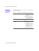
Figure 1-1 Chassis Front Panel
Table 1-2 SCOPIA Elite 5100 Series Panel Features
Component Description
1 STATUS LED Lights green to indicate normal operation. Lights red to
indicate that an error has occurred and that the Media
Blade requires resetting.
2 Serial connector A DB-9 connector that allows you to connect a PC
terminal for local configuration, maintenance and
debugging.
3 100/1000 BASE-T
Ethernet connectors
RJ-45 connectors that provide the primary LAN
connection for the IP network port.
4 Ethernet connector
Link/Activity LEDs
The top part of each Ethernet connector contains two LED
indicators. The right LED lights green when the local IP
network link is active. The left LED lights green if the
connection speed reaches 1000 Mbps, and lights orange if
the connection speed reaches 100 Mbps.
5 Reset Button Enables you to reset the MCU manually.
6 Power LED Lights green to indicate that the power is turned on.