Platform Guide 6&23,$ (/,7( 6HULHV
NOTICE © 2005-2009 RADVISION Ltd. All intellectual property rights in this publication are owned by RADVISION Ltd and are protected by United States copyright laws, other applicable copyright laws and international treaty provisions. RADVISION Ltd retains all rights not expressly granted. This publication is RADVISION confidential. No part of this publication may be reproduced in any form whatsoever or used to make any derivative work without prior written approval by RADVISION Ltd.
CONTENTS About This Manual 1 2 3 4 Related Documentation v Feedback v SCOPIA Elite 5100 Series Platform Overview SCOPIA Elite 5100 Series Chassis Main Features 2 SCOPIA Elite 5100 Series Front and Back Panel Display 3 Cable Connections and Pin-outs 9-Pin Serial Port Terminal Cable 5 RJ-45 8-Pin IP Network Port 100 Mbps Ethernet 1 Gbps Ethernet 6 6 6 Safety Installation Safety 9 Electrical Safety Grounding ESD Procedures 10 10 11 Operation Safety 11 Compliance and Certifications Safet
iv EMC FCC Part 15 Notice 13 14 Environmental Compliance 14 SCOPIA Elite 5100 Series Platform Guide
ABOUT THIS MANUAL The SCOPIA Elite 5100 Series platform guide provides information on the SCOPIA Elite 5100 Series platform and its components. For information and operating procedures pertaining to a specific element board or application, refer to the corresponding manual provided with the product. RELATED DOCUMENTATION The SCOPIA Elite 5100 Series platform documentation set is available on the RADVISION Utilities and Documentation CD-ROM supplied with the product and includes manuals in PDF format.
vi SCOPIA Elite 5100 Series Platform Guide
1 SCOPIA ELITE 5100 SERIES PLATFORM OVERVIEW The SCOPIA Elite 5100 Series platform is a high performance chassis that enables scheduled and ad-hoc high definition conferencing at up to 1080p and meets a wide variety of functional and performance application requirements. The SCOPIA Elite 5100 Series platform provides a wide range of video layouts and powerful audio and video transcoding.
SCOPIA Elite 5100 Series Chassis Main Features SCOPIA ELITE 5100 SERIES CHASSIS MAIN FEATURES The SCOPIA Elite 5100 chassis is a 1U chassis that contains one RADVISION SCOPIA Elite Media Blade. Table 1-1 Main Features of the SCOPIA Elite 5100 Series Chassis Grounding and electrostatic discharge Cooling Power supply The chassis supports a single failed fan in the fan tray.
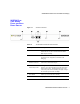
SCOPIA Elite 5100 Series Front and Back Panel Display SCOPIA ELITE 5100 SERIES FRONT AND BACK PANEL DISPLAY Figure 1-1 Chassis Front Panel Table 1-2 SCOPIA Elite 5100 Series Panel Features Component Description 1 STATUS LED Lights green to indicate normal operation. Lights red to indicate that an error has occurred and that the Media Blade requires resetting. 2 Serial connector A DB-9 connector that allows you to connect a PC terminal for local configuration, maintenance and debugging.
SCOPIA Elite 5100 Series Front and Back Panel Display Figure 1-2 4 SCOPIA Elite 5100 Series Platform Guide Chassis Rear Panel
2 CABLE CONNECTIONS AND PIN-OUTS 9-PIN SERIAL PORT TERMINAL CABLE 9-Pin Serial Port Terminal Cable on page 5 RJ-45 8-Pin IP Network Port on page 6 Table 2-1 describes the pin-to-pin configuration of the RS-232 terminal cable provided with the SCOPIA Elite 5100 Series.
RJ-45 8-Pin IP Network Port RJ-45 8-PIN IP NETWORK PORT 100 MBPS ETHERNET 100 Mbps Ethernet on page 6 1 Gbps Ethernet on page 6 Table 2-2 describes the pin-out configuration of the 100 Mbps RJ-45 Ethernet connector. Table 2-2 1 GBPS ETHERNET Pin Function I/O 1 TXD+ Output 2 TXD+ Output 3 RXD+ Input 4 NC 5 NC 6 RXD- 7 NC 8 NC Input Table 2-2 describes the pin-out configuration of the 1 Gbps RJ-45 Ethernet connector.
RJ-45 8-Pin IP Network Port Pin Name Function I/O 5 BI_DC- Bi-directional pair C - I/O 6 BI_DB- Bi-directional pair B - I/O 7 BI_DD+ Bi-directional pair D + I/O 8 BI_DD- Bi-directional pair D - I/O Cable Connections and Pin-outs 7
RJ-45 8-Pin IP Network Port 8 SCOPIA Elite 5100 Series Platform Guide
3 SAFETY This section describes safety procedures and requirements for operating the SCOPIA Elite 5100 Series platform. INSTALLATION SAFETY Installation Safety on page 9 Electrical Safety on page 10 Operation Safety on page 11 Read the installation instructions before connecting the system to the power source. To avoid an electric shock or damage to the SCOPIA Elite 5100 Series platform, servicing should be performed by qualified service personnel only. Do not operate without covers.
Electrical Safety ELECTRICAL SAFETY To reduce the risk of damaging power surges, RADVISION recommends installing an AC surge arrestor in the AC outlet from which the SCOPIA Elite 5100 Series platform is powered. A readily accessible listed branch circuit over current protective device rated 20 A must be incorporated in the building wiring. GROUNDING Grounding on page 10 ESD Procedures on page 11 This SCOPIA Elite 5100 Series platform must be grounded.
Operation Safety Advarsel Apparatet må tilkoples jordet stikkontakt. Varning Apparaten skall anslutas till jordat uttag. ESD PROCEDURES To prevent damage to RADVISION element boards by random electrostatic discharge (ESD), the use of wrist straps is highly recommended. OPERATION SAFETY Warning To prevent the SCOPIA Elite 5100 Series platform from overheating, do not operate it in an area that exceeds the maximum recommended ambient temperature of 113°F (45°C).
Operation Safety 12 SCOPIA Elite 5100 Series Platform Guide
4 COMPLIANCE AND CERTIFICATIONS This section provides certifications that have been approved for the SCOPIA Elite 5100 Series platform. SAFETY COMPLIANCE EMC Safety Compliance on page 13 EMC on page 13 Environmental Compliance on page 14 This section lists the safety standards supported by the SCOPIA Elite 5100 Series platform. IEC 60950-1 2nd Edition UL 60950-1 2nd Edition CAN/CSA C22.2 No.
Environmental Compliance AS/NZS 3548, Class A VCCI, Class A CISPR22, Class A Warning This is a class A product. In a domestic environment this product may cause radio interference in which case the user may be required to take adequate measures. FCC PART 15 NOTICE This section provides RF interference information for the user. This equipment has been tested and found to comply with the limits for a Class A digital device, pursuant to Part 15 of the FCC rules.
About RADVISION RADVISION (NASDAQ: RVSN) is the industry’s leading provider of market-proven products and technologies for unified visual communications over IP and 3G networks.