SCOPIA Elite 5100 Series MCU Installation Guide Version 7.
© 2000-2011 RADVISION Ltd. All intellectual property rights in this publication are owned by RADVISION Ltd and are protected by United States copyright laws, other applicable copyright laws and international treaty provisions. RADVISION Ltd retains all rights not expressly granted. All product and company names herein may be trademarks of their registered owners. This publication is RADVISION confidential.
1 Table of Contents 1 About the SCOPIA Elite MCU Main Features of the SCOPIA Elite MCU .................................................................. 1 Technical Specifications .................................................................................... 5 2 Planning your MCU Deployment Planning your Distributed or Centralized Topology for MCU .......................................... 7 Ports to Open for the SCOPIA Elite 5100 Series MCU.................................................
Attaching Brackets to the MCU..................................................................... 22 Marking the Location of the Device-fixing Cage Nuts .......................................... 23 Removing the Cage Nut Screws .................................................................... 24 Mounting the Device-fixing Cage Nuts ............................................................ 24 Mounting the MCU onto the Shelf..................................................................
1 About the SCOPIA Elite MCU The SCOPIA Elite MCU enables multimedia, multiparty collaboration in applications such as group conferencing, distance learning, training and video telephony. The MCU supports multimedia, multiparty communications in the board room, at the desktop, in the home, or on the road over wireless. • Main Features of the SCOPIA Elite MCU ..................................................... • Technical Specifications ...................................................................
Figure 1-1 Various devices are used in the same conference • Seamless interoperability with leading telepresence systems The MCU can easily connect to telepresence systems and combine them with regular videoconferencing systems, even within the same call. The MCU is compatible with telepresence systems from Cisco, Tandberg, Polycom, and LifeSize/Logitech. Enhanced video layouts were specifically designed for telepresence systems.
– – – – – – A choice of 24 video layouts H.263 and H.264 in the same conference Resolutions from QCIF to 1080p in the same conference Framerate of up to 60 fps for 720p resolution and 30 fps for other resolutions Up to 12Mbps on each stream without affecting capacity MCU’s bandwidth estimation package improves call quality over Internet connections. The available bandwidth is estimated at the beginning of each call and adjusts accordingly during the call.
• In-conference control During a conference, participants can use their endpoint remote control or keypad to perform actions such as mute, volume control, changing video layouts and inviting participants. These options are presented in the in-meeting menu displayed on top of the video layout. • Optional no self see The no self-see (NSS) option is enabled by default, but can be disabled with an advanced command. This feature enables more effective use of the video screen.
Technical Specifications This section lists important data about the system you purchased. Refer to this data when preparing system setup and afterwards as a means of verifying that the environment still complies with these requirements. • System power requirements: – – – – 90-264VAC input, 50/60Hz Single 400W AC power supply (default) / 48V DC power supply Power consumption of a media blade: max. 250W (50°C) Power consumption of an MCU including the chassis, control blade, and AC power supply: max.
– – – – Codecs—H.261, H.263, H.263+, H.264, H.264 SVC Live video resolutions—QCIF up to 1080p Presentation video resolution—VGA, SVGA, SXGA, 720p, 1080p, WUXGA Video bandwidth—up to 12Mbps for 1080p resolutions and up to 6Mbps for 720p or lower • Call capacity: See Table 1-1 on page 6 for the list of MCU call capacity licenses.
2 Planning your MCU Deployment When planning your MCU deployment, it is important to consider both bandwidth usage and port security, as described in the following sections: • Planning your Distributed or Centralized Topology for MCU ............................. page 7 • Ports to Open for the SCOPIA Elite 5100 Series MCU.....................................
Figure 2-1 Centralized MCU deployment, where all branches use the HQ MCU To reduce cross-site bandwidth costs, a distributed MCU deployment (Figure 2-2 on page 9) can perform cascaded conferences, where local participants connect to their local MCU, and the conference is cascaded by connecting between the MCUs using a fraction of the bandwidth compared to the centralized deployment. Users of distributed MCU deployments do not need to choose a specific MCU.
Figure 2-2 Distributed MCU deployment enabling reduced WAN bandwidth SCOPIA iVIEW Management Suite’s sophisticated cascading algorithms enable administrators to customize the priority given to cascading in a distributed topology. There are a number of factors that might influence when the system chooses to cascade to a different MCU. For example, if the maximum bandwidth threshold is breached, the system would attempt cascading with a different MCU.
Ports to Open for the SCOPIA Elite 5100 Series MCU The SCOPIA Elite 5100 Series MCU is typically located in the enterprise network and is connected to the DMZ. When opening ports on the SCOPIA Elite 5100 Series MCU, use the following as a reference: • If you are opening ports that are both in and out of the SCOPIA Elite 5100 Series MCU, see Table 2-1. • If you are opening ports outbound from the SCOPIA Elite 5100 Series MCU, see Table 2-2.
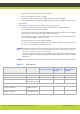
Port Range Protocol Destination Functionality 3336 XML (TCP) Conference Control web client endpoint, iVIEW Management Suite, or third-party controlling applications Enables you to Cannot use MCU Mandatory if deployed with manage the MCU via Conference Control iVIEW Management Suite the XML API web user interface. Cannot use XML API to control MCU.
Table 2-2 Outbound Ports to Open from the SCOPIA Elite 5100 Series MCU Port Range Protocol Destination 162 SNMP (UDP) iVIEW Network Enables sending Manager, iVIEW SNMP Trap events Management Suite, or any SNMP manager station Table 2-3 Port Range Protocol Functionality Result of Blocking Port Required Cannot send SNMP Traps Recommended Inbound Ports to Open to the SCOPIA Elite 5100 Series MCU Destination Functionality Result of Blocking Port Required 21 FTP (TCP) FTP Server Enables audi
3 Preparing the MCU Setup Perform procedures in this section to prepare the site and device for installation. • Checking Site Suitability ...................................................................... • Unpacking the Device ......................................................................... • Inspecting for Damage ........................................................................
Unpacking the Device We strongly recommend that you follow safety guidelines described in this section during unpacking. Procedure Step 1 Step 2 Inspect the shipping box to verify that it is not seriously damaged during shipping. Place the shipping box on a horizontal surface paying attention to the This Side Up symbol on the shipping box. See Figure 3-1 on page 14.
Step 8 Carefully open the additional boxes, remove the packing material, and remove the drives and other contents. Note: Step 9 We recommend that you keep the packaging materials in case you need to repack the device. After opening the shipping box, check the shipment is complete. Compare the contents of the shipment with your packing list.
4 Setting up the MCU Mount the device onto a 19” square-hole rack. Use a shelf to support the device in the rack (Figure 4-1 on page 16). Figure 4-1 Shelf mounted MCU These sections describe how to set up the device: • Verifying Rack Suitability ..................................................................... • Complying with MCU Lifting Guidelines .................................................... • Mounting the MCU onto the Rack Using a Shelf ...........................................
Verifying Rack Suitability There are some critical requirements that you must meet when choosing a rack and before mounting the device into it. • Choosing the Type of Rack.................................................................... page 17 • Making Space for the MCU .................................................................... page 17 Choosing the Type of Rack There are many types of racks on the market. The installation instructions in this guide are intended for a 19” rack.
• Find a space on the rack which is at least 7 empty square holes in height on the rack posts. The MCU takes up 3 holes (1U) on the posts. You need at least 2 additional holes to slide the device into the rack. See Figure 4-3 on page 18. Figure 4-3 Height of the MCU in the rack • To mount the MCU between two posts, the width between the inner sides of the two posts must be at least 17.7 inches (45 cm). See Figure 4-4 on page 18.
Complying with MCU Lifting Guidelines The device is very heavy and is not intended to be moved frequently. Before you install the device, ensure that your site is properly prepared, so you can avoid having to move the chassis later to accommodate for power sources and network connections. Whenever you lift the chassis or any heavy object, follow these guidelines: • Always disconnect all external cables before lifting or moving the MCU.
Locating a Shelf in the Rack Before choosing a shelf that will support the device, follow this procedure. Procedure Step 1 Read “Verifying Rack Suitability” on page 17, which contains important positioning and spacing information. Step 2 Prepare masking tape or a felt-tip pen to mark the location of the device-fixing cage nuts. If the holes on the rack are marked with numbers, write down the numbers on a piece of paper.
Checking the Accessories Required for Mounting Check you have the accessories necessary for mounting the device (see Figure 4-6 on page 21): • 2 mounting brackets (left and right) • 4 cage nuts (M6) each with its hexagon socket cap screw (M6x10, DIN 7984) • 8 Phillips screws. Note: Make sure you have a ruler, an Allen wrench (4 mm diameter), and a screwdriver (Nr. 1 tip) ready to hand before you start the setup.
Attaching Brackets to the MCU The brackets serve to secure the device to the rack’s front posts. Procedure Step 1 Position the device on a flat, horizontal surface. Make sure the device front panel faces toward you. Step 2 Unscrew the four black Phillips screws on either side of the device. See Figure 4-7 on page 22. Figure 4-7 Removing the Phillips screws on the side panel Step 3 Attach the brackets on each side of the device side panel with the Phillips screws. See Figure 4-8 on page 22.
Marking the Location of the Device-fixing Cage Nuts There is an extra pair of cage nuts for each front-facing rack post. You need these cage nuts to fix the device brackets to the post. Before attaching the cage nuts to the rack, mark where you plan to attach them, so you can be sure they are level and properly placed. Procedure Step 1 From inside the front-facing rack post, mark the location of the lower device-fixing cage nut measured at 0.20 inches (0.5 cm) above the shelf. See Figure 4-9 on page 23.
Removing the Cage Nut Screws The cage nuts are supplied with pre-mounted screws. Remove the screws and put them aside for later. See Figure 4-10 on page 24. Figure 4-10 Removing the cage nut screw Mounting the Device-fixing Cage Nuts After you have marked the location of these cage nuts on the front-facing posts, you can mount them into the rack. Insert each cage nut on each of the posts where you have placed marks on the rack.
Procedure Step 1 Lift the device according to the instructions in “Complying with MCU Lifting Guidelines” on page 19. Step 2 Slide the device onto the shelf until the holes on the device’s brackets align with the cage nuts you mounted previously. See Figure 4-11 on page 25. Figure 4-11 Sliding the MCU onto the shelf Step 3 Insert the four remaining screws you set aside through the bracket holes into the cage nuts in the rack.
Figure 4-12 Securing the MCU to the rack Attaching the System Ground Note: WARNING - Before connecting power to the device or turning it on, provide it with an adequate connection to a grounding point at the site. Contact the appropriate electrical inspection authority or an electrician if you are uncertain that suitable grounding is available on the site. The MCU grounding stud is located on the rear panel.The grounding equipment is user supplied.
b. On the rear side of the device, plug in the power cable into the AC power connector (see Figure 4-13 on page 27). Figure 4-13 Rear panel of the device c. Plug in the other end of the power cable into the mains. d. Power on the device using the On/Off switch on the rear side of the device (see Figure 4-13 on page 27). Figure 4-14 Device front panel e. Turn on the power distribution unit (PDU). RADVISION | Installation Guide for SCOPIA Elite 5100 Series MCU Version 7.
Step 2 Connect a network cable to the left Ethernet connector on the front side of the device (see Figure 4-14 on page 27) Note: Step 3 Use both Ethernet connectors for dual-NIC deployments. A dual-NIC MCU raises security by using different subnets for media and management. Use the left Ethernet connector for management and the right connector for media. For more information, see the Configuring a Dual-NIC MCU section in the Installation Guide for the SCOPIA Elite MCU.
5 Performing the MCU Initial Configuration When you finish installing the MCU, you need to perform the initial configuration during which you configure the basic features. After the initial configuration the MCU should be ready for use. • Setting the IP Address ......................................................................... • Accessing the MCU Administrator Interface ............................................... • Changing a User Password ......................................................
Procedure Step 1 Step 2 Step 3 Step 4 Step 5 Connect the serial cable from the PC terminal to the serial port on the front panel of the MCU. Connect the power cable. Start the terminal emulation application (such as SecureCRT or PuTTY) on the PC. Set the communication settings in the terminal emulation application on the PC as follows: • Baud rate: 9600 • Data bits: 8 • Parity: None • Stop bits: 1 • Flow control: None Turn on the power to the MCU.
Figure 5-2 Setting the IP Address Step 12 Step 13 Step 14 Step 15 Step 16 Step 17 Step 18 Step 19 Step 20 Enter the subnet mask without leading zeros at the Subnet mask prompt and then press Enter. Enter the IP address of the router associated with the segment in which the unit will be installed at the Default Router prompt and press Enter. Press Enter at the Preferred DNS prompt. Press Enter at the Alternate DNS prompt. Press Enter at the DNS suffix prompt. Enter Y. Enter Q at the prompt and press Enter.
Accessing the MCU Administrator Interface The MCU interface is available in these languages: • English • Chinese • Japanese • Portuguese • Spanish • Russian The default language of the MCU interface is English. When you access the MCU interface, the login screen is in English unless you choose a different language. Procedure Step 1 Step 2 Launch your browser and enter the IP address or the name of the MCU. If you need to change the MCU interface language, select a language from the Language list.
Procedure Step 1 Step 2 Step 3 Step 4 Step 5 Access the MCU Administrator interface. Select Users . Select the Review button for the user profile you want to modify. Enter the new password in the Password and the Confirm Password fields. Select Apply. Changing the MCU Service Prefix The MCU comes with a single predefined default service (with prefix number 71). The predefined service is factory tuned to be suitable in most cases for audio and video calls.
About Supported Languages The MCU has three user interfaces: • Administrator interface—the web-based interface used by administrators for configuration and maintenance tasks. • Conference Control interface—the web-based interface used by administrators and operators for conference moderation and video layout control. • Text overlay on conference video—the set of menus that appear in the conference video.
Procedure Step 1 Select Configuration in the MCU user interface. The Setup tab is displayed. Step 2 Step 3 Locate the Basics section. Select a language in the Default user interface language list. Figure 5-3 Basics section of the Setup tab Step 4 Select Apply at the bottom of the Setup tab. Setting a Text Overlay Language Perform the procedure in this section to set the language of the text overlay messages. The text overlay feature is set to English by default.
Configuring Protocols for the MCU Set the MCU protocols by configuring it to work either with the H.323 gateway or with the SIP Proxy Server, or with both. You can change the protocol-related settings at any time without resetting the MCU. • Configuring H.323 Protocol Settings ........................................................ page 36 • Configuring SIP Server Settings .............................................................. page 37 Configuring H.323 Protocol Settings You can configure the H.
Figure 5-6 The Status Map showing the Gatekeeper connection d. Verify that the MCU is connected to the Ethernet. e. Verify that the MCU is connected to the Gatekeeper. Configuring SIP Server Settings You can configure settings for SIP server profiles which set how the MCU and the registrar interact.
Step 5 Select Locate automatically to instruct the MCU to automatically locate one of the SIP servers that are present in the domain, or Select Specify and enter the following: • An IP address or host name of the SIP server, for example ..com. Figure 5-7 SIP Protocol section of the Protocols tab • The communication port number of the SIP server address. The default port is 5060. • The transport connection type. The default is UDP.
b. Enter the following information: • The IP address or the host name of the SIP registrar in the IP address field. • The communication port number of the SIP registrar address. • The transport connection type for sending registration requests to the registrar according to the type supported by the SIP registrar. The default is UDP. Step 7 Select More. The Local signaling port section is displayed.
Step 10 Select Use registrar digest authentication to enable MCU authentication with a SIP registrar using user name and password. Authentication is performed as defined in RFC 2617. This field is disabled by default. Enter the MCU user name and password. They must match those defined on the SIP server. Step 11 Select Use ‘Empty Invite’ when sending Invite messages to endpoints to enable the remote endpoint to indicate preferred audio and video channels. Step 12 Step 13 Select Apply.
Dual-NIC functionality requires two subnets, where each subnet must have its own router or default gateway. Procedure Step 1 Connect the network cable of the management subnet to the left ethernet port only, and activate the unit. Figure 5-11 Two Ethernet connectors of the SCOPIA Elite MCU Note: Step 2 Step 3 Do not connect the media subnet cable until the MCU has been reset at the end of this procedure. Access the MCU in a web browser and login.
Step 4 Select the Advanced IP (Dual-NIC) Configuration check box to expand that section of the page. Figure 5-12 Dual-NIC configuration for management and media subnets Step 5 Under Management Interface, enter the IP information for the management subnet: a. Enter the MCU’s IP address on the management subnet in the Primary IP address field. b. Enter the IP address of the management subnet’s router in the Router IP field.
Configuring Ports on All Models of the SCOPIA Elite MCU This section provides instructions of how to configure the following ports and port ranges on the SCOPIA Elite MCU 5000 Series, including the SCOPIA Elite 5100 Series MCU and the SCOPIA Elite 5200 Series MCU: • Limiting the UDP Port Ranges for RTP/RTCP on the SCOPIA Elite MCU ............... page 43 • Configuring the TCP Port Range for H.245 on the SCOPIA Elite MCU .................. page 44 • Configuring the HTTP Port on the SCOPIA Elite MCU ........
Figure 5-13 CLI Section Step 2 Set the video base port by doing the following: a. Enter the advcmdmpcsetval command in the Command field. b. Enter the mf.BasePort parameter in the Parameter field. c. Enter the port value in the Value field. d. Select Execute. e. Clear the value in the Parameter field before proceeding to the next step. Step 3 Set the audio base port by doing the following: a. Enter the setmprtpbaseport command in the Command field. b. Modify the port value in the Value field. c.
c. Locate the CLI section and select More (see Figure 5-13 on page 44). Figure 5-14 CLI Section Step 2 Enter the h245baseport command in the Command field. Note: Step 3 Step 4 Step 5 To see the current port value, select Execute. Modify the port value in the Value field. Select Execute. Select Close. Configuring the HTTP Port on the SCOPIA Elite MCU The SCOPIA Elite MCU 5000 Series has designated port 80 for HTTP. You can configure a different port to use HTTP if necessary in your environment.
Figure 5-15 CLI Section Step 2 Enter the webserverport command in the Command field. Note: Step 3 Step 4 Enter the port value in the Value field. Select Execute. Note: Step 5 Step 6 To see the current port value, select Execute. After selecting Execute, a warning message appears, notifying you that the unit will be reset and any active conferences will be disconnected. Select Yes to continue. Select Close.
Configuring the UDP Port for RAS on the SCOPIA Elite MCU The SCOPIA Elite MCU 5000 Series has designated port 1719 for RAS. You can configure a different port to use RAS (for example, if port 1719 is busy). Port 1719 is also used to communicate with the gatekeeper (to configure the UDP port for the gatekeeper, see “Configuring the UDP Port for the Gatekeeper on the SCOPIA Elite MCU” on page 48). Note: If you close port 1719, you must configure another port for both RAS and the gatekeeper.
Configuring the UDP Port for the Gatekeeper on the SCOPIA Elite MCU The SCOPIA Elite MCU 5000 Series has designated port 1719 for gatekeeper use. You can configure a different port to enable communication with the gatekeeper (for example, if port 1719 is busy). Port 1719 is also used for RAS (to configure the UDP port for RAS, see “Configuring the UDP Port for RAS on the SCOPIA Elite MCU” on page 47). Note: If you close port 1719, you must configure another port for both the gatekeeper and RAS.
Figure 5-18 H.323 Signaling Port Configuration Step 2 Step 3 Step 4 Step 5 Select the icon in the Review column. Enter the port value in the H323 SIG port number field. Select Apply. Select Close. RADVISION | Installation Guide for SCOPIA Elite 5100 Series MCU Version 7.
Configuring the TCP/UDP/TLS Port for SIP on the SCOPIA Elite MCU The SCOPIA Elite MCU 5000 Series has designated ports 5060 and 5061 for SIP. You can configure a different port to use SIP (for example, if port 5060 or 5061 is busy). Procedure Step 1 Step 2 Navigate to the MCU SIP Protocol section by selecting Configuration > Protocols. Locate the Enable SIP protocol section and select More (see Figure 5-19 on page 50).
Configuring Security Access Levels for the SCOPIA Elite MCU The SCOPIA Elite MCU offers configurable security access levels that enable and disable SSH, FTP, SNMP and ICMP (ping) protocols. By default, the security access level is set to Standard. It is recommended to set your security access level to Maximum (which disables these protocols), except for the following situations: • If you are performing either debugging or troubleshooting operations, SSH should be enabled.
Verifying the MCU Installation After you installed the device and performed its initial configuration, you need to verify that it is installed and configured correctly. Procedure Step 1 On the front panel, verify that the power alarm LED is lit green lower down on the unit. Figure 5-21 Locating the front panel LEDs Step 2 Step 3 On the front panel, verify that the status LED is lit green. Check the network connection by verifying that the Ethernet activity LED is lit green.
www.radvision.com About RADVISION RADVISION (NASDAQ: RVSN) is the industry’s leading provider of market-proven products and technologies for unified visual communications over IP, 3G and IMS networks.