SCOPIA Elite 5100 Series MCU Administrator Guide Version 7.
© 2000-2011 RADVISION Ltd. All intellectual property rights in this publication are owned by RADVISION Ltd and are protected by United States copyright laws, other applicable copyright laws and international treaty provisions. RADVISION Ltd retains all rights not expressly granted. All product and company names herein may be trademarks of their registered owners. This publication is RADVISION confidential.
1 Table of Contents 1 About the SCOPIA Elite MCU Main Features of the SCOPIA Elite MCU .................................................................. 1 Technical Specifications .................................................................................... 5 2 Planning your MCU Deployment Planning your Distributed or Centralized Topology for MCU .......................................... 7 Ports to Open for the SCOPIA Elite 5100 Series MCU.................................................
Upgrading Software ....................................................................................... 29 Restoring a Previous Software Version.................................................................. 31 Updating a SCOPIA Elite 5100 Series MCU License.................................................... 32 Configuring Ports on All Models of the SCOPIA Elite MCU ........................................... 33 Limiting the UDP Port Ranges for RTP/RTCP on the SCOPIA Elite MCU......................
Resolving Quality Issues in Cascaded Conferences ................................................... 62 Resolving Endpoint Disconnection Issues ............................................................... 63 Resolving Unexpected Conference Termination....................................................... 63 Resolving Presentation Issues ............................................................................ 64 Resolving Unexpected SIP Call Disconnection .............................................
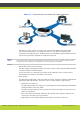
1 About the SCOPIA Elite MCU The SCOPIA Elite MCU enables multimedia, multiparty collaboration in applications such as group conferencing, distance learning, training and video telephony. The MCU supports multimedia, multiparty communications in the board room, at the desktop, in the home, or on the road over wireless. • Main Features of the SCOPIA Elite MCU ..................................................... • Technical Specifications ...................................................................
Figure 1-1 Various devices are used in the same conference • Seamless interoperability with leading telepresence systems The MCU can easily connect to telepresence systems and combine them with regular videoconferencing systems, even within the same call. The MCU is compatible with telepresence systems from Cisco, Tandberg, Polycom, and LifeSize/Logitech. Enhanced video layouts were specifically designed for telepresence systems.
– – – – – – A choice of 24 video layouts H.263 and H.264 in the same conference Resolutions from QCIF to 1080p in the same conference Framerate of up to 60 fps for 720p resolution and 30 fps for other resolutions Up to 12Mbps on each stream without affecting capacity MCU’s bandwidth estimation package improves call quality over Internet connections. The available bandwidth is estimated at the beginning of each call and adjusts accordingly during the call.
• In-conference control During a conference, participants can use their endpoint remote control or keypad to perform actions such as mute, volume control, changing video layouts and inviting participants. These options are presented in the in-meeting menu displayed on top of the video layout. • Optional no self see The no self-see (NSS) option is enabled by default, but can be disabled with an advanced command. This feature enables more effective use of the video screen.
Technical Specifications This section lists important data about the system you purchased. Refer to this data when preparing system setup and afterwards as a means of verifying that the environment still complies with these requirements. • System power requirements: – – – – 90-264VAC input, 50/60Hz Single 400W AC power supply (default) / 48V DC power supply Power consumption of a media blade: max. 250W (50°C) Power consumption of an MCU including the chassis, control blade, and AC power supply: max.
– – – – Codecs—H.261, H.263, H.263+, H.264, H.264 SVC Live video resolutions—QCIF up to 1080p Presentation video resolution—VGA, SVGA, SXGA, 720p, 1080p, WUXGA Video bandwidth—up to 12Mbps for 1080p resolutions and up to 6Mbps for 720p or lower • Call capacity: See Table 1-1 on page 6 for the list of MCU call capacity licenses.
2 Planning your MCU Deployment When planning your MCU deployment, it is important to consider both bandwidth usage and port security, as described in the following sections: • Planning your Distributed or Centralized Topology for MCU ............................. page 7 • Ports to Open for the SCOPIA Elite 5100 Series MCU.....................................
Figure 2-1 Centralized MCU deployment, where all branches use the HQ MCU To reduce cross-site bandwidth costs, a distributed MCU deployment (Figure 2-2 on page 9) can perform cascaded conferences, where local participants connect to their local MCU, and the conference is cascaded by connecting between the MCUs using a fraction of the bandwidth compared to the centralized deployment. Users of distributed MCU deployments do not need to choose a specific MCU.
Figure 2-2 Distributed MCU deployment enabling reduced WAN bandwidth SCOPIA iVIEW Management Suite’s sophisticated cascading algorithms enable administrators to customize the priority given to cascading in a distributed topology. There are a number of factors that might influence when the system chooses to cascade to a different MCU. For example, if the maximum bandwidth threshold is breached, the system would attempt cascading with a different MCU.
Ports to Open for the SCOPIA Elite 5100 Series MCU The SCOPIA Elite 5100 Series MCU is typically located in the enterprise network and is connected to the DMZ. When opening ports on the SCOPIA Elite 5100 Series MCU, use the following as a reference: • If you are opening ports that are both in and out of the SCOPIA Elite 5100 Series MCU, see Table 2-1. • If you are opening ports outbound from the SCOPIA Elite 5100 Series MCU, see Table 2-2.
Port Range Protocol Destination Functionality 3336 XML (TCP) Conference Control web client endpoint, iVIEW Management Suite, or third-party controlling applications Enables you to Cannot use MCU Mandatory if deployed with manage the MCU via Conference Control iVIEW Management Suite the XML API web user interface. Cannot use XML API to control MCU.
Table 2-2 Outbound Ports to Open from the SCOPIA Elite 5100 Series MCU Port Range Protocol Destination 162 SNMP (UDP) iVIEW Network Enables sending Manager, iVIEW SNMP Trap events Management Suite, or any SNMP manager station Table 2-3 Port Range Protocol Functionality Result of Blocking Port Required Cannot send SNMP Traps Recommended Inbound Ports to Open to the SCOPIA Elite 5100 Series MCU Destination Functionality Result of Blocking Port Required 21 FTP (TCP) FTP Server Enables audi
3 Maintaining the SCOPIA Elite 5100 Series MCU • Securing MCU and iVIEW Management Suite Connection with TLS..................... • Regulating Bandwidth Usage ................................................................. • Configuring the Auto Attendant Service.................................................... • Configuring the Conference Mode........................................................... • Customizing the Logo Displayed in MCU Conferences....................................
Securing MCU with TLS in a SIP Environment The first step to allow a secure connection between MCU and iVIEW Management Suite is to enable TLS support on the MCU SIP server. Once MCU SIP server is TLS enabled, a certificate must be uploaded to the MCU to provide identification and encryption keys (see “Uploading TLS Certificates” on page 14). Procedure Step 1 Step 2 Step 3 Step 4 Step 5 Step 6 Log in to the MCU. Select Enable SIP Protocol. Select Specify.
Step 3 Select Manage in the Security section. Figure 3-2 Security Section Step 4 Select Create a new certificate request. For example: Figure 3-3 Create New Certificate Request Step 5 Select Next. RADVISION | Administrator Guide for SCOPIA Elite 5100 Series MCU Version 7.
Step 6 Enter the Organization, Organizational Unit, Email and Common name. For example: • Organization: Company_Name • Organizational Unit: IT • Email: joe@companyname.com • Common name: video.mycompany.com (unique for each MCU) Figure 3-4 Organization Details Step 7 Step 8 Step 9 Select Next. Enter the geographical information as required. For example: • Issued To: Company_Name • Country/Region: United States • State/Province: New York • City/Locality: New York Select Next.
Figure 3-5 Certificate Request Summary Step 10 To generate a certificate request, select Next. Copy certificate request text in text area and paste it to a file. For example, mcu_ca_request.txt. Figure 3-6 Save Certificate Request RADVISION | Administrator Guide for SCOPIA Elite 5100 Series MCU Version 7.
Step 11 Submit this file to your Certification Authority (CA) by e-mail or any other method supported by your organization for your Enterprise CA. You will receive a signed certificate from the CA, for example and the root certificate, for example ca_root.cert. To install the signed certificate: Step 12 Step 13 Select Manage. Select Process the pending request and install the certificate. Figure 3-7 Certificate Status Step 14 Step 15 Select Next.
Step 17 If data is correct, select Finish and the MCU certificate is uploaded successfully. If the data is not correct, select Back to enter the correct data. Figure 3-9 Successful Certificate Upload Step 18 Step 19 Upload the CA root certificate by selecting Upload from the Security section. Select Browse to select the CA root certificate. Figure 3-10 Browse for the CA Root Certificate Step 20 Step 21 Select OK. Copy the certificates to the B2BUA’s CA directory, for example: mcu_ca.cert and ca_root.
Regulating Bandwidth Usage Depending on your network capacity, you may need to adjust bandwidth usage by defining how much bandwidth each call will require. Procedure Step 1 Step 2 Step 3 Select Configuration . Select Conferences . Locate the Services list section. Figure 3-11 Service List Section of the Conferences Tab Step 4 Step 5 Select the Review button next to the service. Select the required value from the list under Max call rate (Kbps).
Configuring the Conference Mode The default conference mode is Continuous Presence. To increase your call capacity or conserve bandwidth, you can configure a service to apply one of the following conference modes to your conference: • Audio only • Switched video Procedure Step 1 Step 2 Step 3 Select Configuration Select Conferences . . Locate the Services List section. Figure 3-13 Service List Section of the Conferences Tab Step 4 Step 5 Select Review for the service you want to configure.
Figure 3-14 Service Setting Section Step 6 Select Apply. Configuring the Auto Attendant Service The auto attendant service allows MCU users to create or join a conference even if they do not know the MCU service number or the meeting ID number. The auto attendant number serves as a preconfigured number a user can dial to access the MCU to then either create a new conference or join a conference currently hosted at this MCU. Procedure Step 1 Step 2 Step 3 Select Configuration Select Conferences . .
Step 5 Select the Set as the Auto attendant service link. Figure 3-16 Service Setting Section Step 6 Select Apply. Customizing the Logo Displayed in MCU Conferences Perform the procedure in this section to customize the default logo displayed in the auto-attendant and the MCU conference screens. Procedure Step 1 Step 2 Step 3 Select Configuration . Select Customization. Locate the Images pack area (Figure 3-17 on page 23).
Step 6 Add your logo image to each folder, as follows: Note: It is easier to do this procedure if you open the zip file in Windows Explorer. Images are separated into folders according to resolution (Figure 3-18 on page 24). You need to save the desired logo with each of the specified resolutions to the relevant folder. If any of the images are missing or not in the correct format, the default system logo is used. Figure 3-18 Image Pack Folder Structure a.
Table 3-1 Logo Image Dimensions Resolution File Dimension (in Pixels) 4CIF 216 x 44 1080p 312 x 64 352p 132 x 24 480p 132 x 24 720p 216 x 44 CIF 132 x 24 QCIF 96 x 16 b. Give your image a filename in the following format (maximum characters allowed in the filename is 32): logo_XX Step 7 Step 8 Step 9 Step 10 Step 11 Update the Image pack file by selecting Browse and navigating to your updated .zip file. Select Apply. Select the icon. Select Advanced Parameters.
How to Manage SCOPIA Elite MCU User Profiles Only administrators can manage MCU user profiles. • About SCOPIA Elite MCU User Types ........................................................ page 26 • Adding a User Profile .......................................................................... page 26 • Changing a User Password .................................................................... page 27 • Deleting a User Profile ........................................................................
Procedure Step 1 Step 2 Access the MCU Administrator interface. Select Users . Figure 3-20 Authorized Users List Step 3 Select Add new user. Figure 3-21 User Profile Section Step 4 Step 5 Step 6 Step 7 Select an authority level from the list. Enter a user name. Enter a password and confirm it. Select Apply. Changing a User Password Only administrators can change a password. The MCU comes with two preconfigured users: an administrator and an operator.
Deleting a User Profile Only administrators can delete user profiles. You can delete user profiles at any time. Procedure Step 1 Step 2 Access the MCU Administrator interface. Select Users . Figure 3-22 Authorized Users List Step 3 Select the Review button for the user profile you want to remove. Figure 3-23 User Profile Section Step 4 Step 5 Select Delete. Select Yes in the message that appears. The user profile is removed from the authorized users list.
Restoring Your Configuration You can import the settings of a saved MCU configuration file from a storage device on your network. You can use the saved configuration file to restore the settings to the current MCU or to configure another MCU. The imported file is a .zip file that includes a .val file and a .xml file. Note: If you are importing a configuration setup from a different MCU that has different login credentials, you will need to enter these new credentials to access the MCU.
If you are upgrading from version 7.0, contact Customer Support. Before You Begin Verify that there are no active conferences hosted on the MCU. Procedure Step 1 (Recommended) Save the current MCU configuration by doing the following: a. In the web user interface, select the icon. b. Select Backup configuration. c. Save the generated .zip file. Step 2 If you are upgrading from version 7.1 to version 7.5, do the following: a. Run the Software Update tool. b. Select the Upgrade to version 7.5 tab.
Restoring a Previous Software Version Perform this procedure to downgrade to the previous MCU software version. We highly recommend that you contact RADVISION Customer Support prior to restoring a previous software version. Before You Begin • If you need to restore version 7.5 or 7.6: On the Status tab, verify that the MCU is connected to the network by checking the Ethernet icon.
Note: Do not import the saved configuration to the MCU, after the downgrade. An older version of the MCU configuration might not support the new configuration values. Step 4 Verify that the MCU functions properly: a. From an endpoint dial the MCU IP address. You access the MCU auto attendant service which plays the video and audio prompts. b. Press 0 to create a new conference. c. At a prompt, enter the meeting ID and press #. The MCU creates the conference and you see the Conference window. d.
Figure 3-25 Licensing and Registration Window Step 5 Step 6 Enter the permanent license key. Select Update. Configuring Ports on All Models of the SCOPIA Elite MCU This section provides instructions of how to configure the following ports and port ranges on the SCOPIA Elite MCU 5000 Series, including the SCOPIA Elite 5100 Series MCU and the SCOPIA Elite 5200 Series MCU: • Limiting the UDP Port Ranges for RTP/RTCP on the SCOPIA Elite MCU ............... page 33 • Configuring the TCP Port Range for H.
Using its full capacity, the SCOPIA Elite 5100 Series MCU uses 180 ports for audio and 540 ports for video, and the SCOPIA Elite 5200 Series MCU uses 360 ports for audio and 1080 ports for video (except for the SCOPIA Elite MCU 5215, which has the same capacity as the SCOPIA Elite 5100 Series MCU). Procedure Step 1 Navigate to the MCU Advanced Commands section by doing the following: a. Select the icon. b. Select Advanced parameters. c.
Configuring the TCP Port Range for H.245 on the SCOPIA Elite MCU The SCOPIA Elite MCU 5000 Series has designated TCP ports 1024-1324 for H.245. You can set the base port, which is the lower end of the port range. H.245 is a Control Protocol used for multimedia communication that enables transferring information about the device capabilities, as well as opening/closing the logical channels that carry media streams. The SCOPIA Elite 5100 Series MCU uses 150 ports for H.
Configuring the HTTP Port on the SCOPIA Elite MCU The SCOPIA Elite MCU 5000 Series has designated port 80 for HTTP. You can configure a different port to use HTTP if necessary in your environment. Procedure Step 1 Navigate to the MCU Advanced Commands section by doing the following: a. Select the icon. b. Select Advanced parameters. c. Locate the CLI section and select More (see Figure 3-26 on page 34). Figure 3-28 CLI Section Step 2 Enter the webserverport command in the Command field.
Step 4 Select Execute. Note: Step 5 Step 6 After selecting Execute, a warning message appears, notifying you that the unit will be reset and any active conferences will be disconnected. Select Yes to continue. Select Close. Note: After applying the new port value, you must enter it as a suffix to the MCU IP address in order to access the web server.
Figure 3-29 RAS Port Configuration Step 2 Step 3 Step 4 Step 5 Select the icon in the Review column. Enter the port value in the H323 RAS port number field. Select Apply. Select Close. Configuring the UDP Port for the Gatekeeper on the SCOPIA Elite MCU The SCOPIA Elite MCU 5000 Series has designated port 1719 for gatekeeper use. You can configure a different port to enable communication with the gatekeeper (for example, if port 1719 is busy).
Configuring the TCP Port Q.931 on the SCOPIA Elite MCU The SCOPIA Elite MCU 5000 Series has designated port 1720 for Q.931. You can configure a different port to use Q.931 (for example, if port 1720 is busy). Q.931 is a telephony protocol used for establishing and terminating the connections in H.323 calls. Procedure Step 1 Navigate to the MCU Advanced Commands section by doing the following: a. Select the icon. b. Select Advanced parameters. c.
Configuring the TCP/UDP/TLS Port for SIP on the SCOPIA Elite MCU The SCOPIA Elite MCU 5000 Series has designated ports 5060 and 5061 for SIP. You can configure a different port to use SIP (for example, if port 5060 or 5061 is busy). Procedure Step 1 Step 2 Navigate to the MCU SIP Protocol section by selecting Configuration > Protocols. Locate the Enable SIP protocol section and select More (see Figure 3-32 on page 40).
Configuring Security Access Levels for the SCOPIA Elite MCU The SCOPIA Elite MCU offers configurable security access levels that enable and disable SSH, FTP, SNMP and ICMP (ping) protocols. By default, the security access level is set to Standard. It is recommended to set your security access level to Maximum (which disables these protocols), except for the following situations: • If you are performing either debugging or troubleshooting operations, SSH should be enabled.
4 How to Moderate a Conference as an Operator As an operator, you can modify a conference using the Conference Control interface. • Conference Control Interface ................................................................ • Becoming a Moderator and Stopping Moderation ......................................... • How to Control Participants in a Conference ............................................. • Defining Conference Views ...................................................................
Figure 4-1 shows the Conference Control page. The layout of the Conference Control page may be different depending on whether you are a moderator or not. If you are not a moderator, you do not have access to moderator tasks. Figures in this section show all interface elements including those which are available for moderators only.
Becoming a Moderator and Stopping Moderation Moderator access can be PIN-protected. Administrators and Operators can jointly be moderators simultaneously. Procedure Step 1 Step 2 Step 3 Step 4 Access the Conference Control interface by clicking Select Become Moderator . to take control of that conference. A dialog box requesting a PIN might appear if Moderator access is PIN-protected. Enter the PIN. To release control of the conference, select Stop Moderation .
Figure 4-2 SCOPIA Elite MCU Login Window b. Select the Create link. c. Select Create Conference. -or- Step 2 To create a conference from the Conference Control interface: a. Access the Conference Control interface by selecting the Manage Conferences button . b. Select Create Conference Step 3 on the toolbar. Select a service prefix from the list. Figure 4-3 Create Conference Page Step 4 Enter an ID number for this conference in the Unique Number field.
Step 6 (Optional) Enter a PIN for moderating the conference in the Moderator PIN field. Note: Step 7 Step 8 Step 9 You can also configure a default moderator PIN for a service profile in the Administrator interface. (Optional) Enter a description of the meeting in the Conference Description field. (Optional) Select Advanced to configure additional settings for the conference such as duration, time-out and dialing policy settings. Select Create to launch your conference.
Muting and Unmuting All Participants Users with moderator level access can mute or unmute all participants in the conference. Procedure Step 1 Access the Conference Control interface by selecting the Manage Conferences button . Step 2 In the Participants List section, select Mute All. Figure 4-4 Mute All Button in the Participant List Section Submenu opens. Figure 4-5 Mute All submenu Step 3 Select the desired option.
Figure 4-6 Change Participant’s View button in the Participant List Tab Procedure Step 1 Step 2 Access the Conference Control interface. To change the view for an individual participant, perform these steps: a. Select the Change Participant’s View button for this participant in the Participant List Tab. Figure 4-7 Change Participant’s View button in the Participant List Tab b. From the submenu, select the necessary option. RADVISION | Administrator Guide for SCOPIA Elite 5100 Series MCU Version 7.
Figure 4-8 Participant View Submenu Note: Step 3 You can display up to 28 participants in a single layout. Layouts that display up to 16 participants are supported by all resolutions, while layouts that display 21 or 28 participants are supported only by resolutions of 480p or higher. To change the view for several participants or all participants, perform these steps: a.
Figure 4-10 Change view dialog box d. From the Change to view list, select the desired view. e. Select OK. Blocking Conference Admission Users with moderator-level access can block the admission of additional participants in a conference in the Conference Control interface. As a result, no further participants can join the conference. Procedure Step 1 Access the Conference Control interface by selecting the Manage Conferences button . Step 2 On the toolbar, select Conference Admission.
The Call Information dialog box for the specified participant appears. Table 4-1 lists the statistics displayed. Table 4-1 Participant Information Statistics Group Field Description Endpoint Information Type Participant endpoint type. IP address Participant endpoint IP address. Description Participant description (displays the endpoint vendor identifier, if available). Connect time Time at which the participant connected to the conference.
Group Field Description Video Video codec Video codecs sent to and received by the participant. Video resolution Picture size of video sent and received by the participant. Video frame rate Frame rate of video sent to and received by the participant. Video rate Total video bandwidth sent and received by the participant. Video packets loss count Total lost video packets sent to and received by the participant.
Group Field Description Video Video out of order packets count Total video packets sent to and received from the participant out of sequence. Video fast update requests count Total Video Fast Update (VFU) requests sent and received by the participant. Video packets count Total video packets sent and received by the participant. Video bytes count Total video packets sent and received by the participant. Video IP address IP address and port to which video is sent to the participant.
Changing the Conference View In the Conference View section, users with moderator-level access can change the main layout for the current conference. Procedure Step 1 Access the Conference Control interface by selecting the Manage Conferences button . Step 2 In the Conference View section of the Participant List tab, select Change. Figure 4-11 Conference View Section The layout menu appears, displaying a list of available layouts for the current conference.
Figure 4-12 Layout Menu Displayed in the Conference View Section Step 3 Select the layout of your choice. Note: You can display up to 28 participants in a single layout. Layouts that display up to 16 participants are supported by all resolutions, while layouts that display 21 or 28 participants are supported only by resolutions of 480p or higher. The conference adjusts to the new selection.
The names are displayed at the bottom of the participants’ frames in a conference (Figure 4-13 on page 56). Figure 4-13 Names Displayed in Conference (Example) RADVISION | Administrator Guide for SCOPIA Elite 5100 Series MCU Version 7.
Enabling the Self-see Feature The self-see feature allows participants see their own video in a separate frame displayed as part of the conference video. By default, this feature is disabled. Procedure Step 1 Step 2 Access the Conference View section of the Participant List tab. Select the Self-see mode button. All participants using the conference view can see themselves in the conference video. RADVISION | Administrator Guide for SCOPIA Elite 5100 Series MCU Version 7.
Terminating Conferences You can terminate a conference at any time. This action disconnects all participants from the conference. Procedure Step 1 Step 2 Access the Conference Control interface. Select Terminate Conference. Figure 4-14 Terminate Conference Button on the Toolbar Step 3 Click OK in the confirmation message. The conference is closed. RADVISION | Administrator Guide for SCOPIA Elite 5100 Series MCU Version 7.
5 Troubleshooting the SCOPIA Elite MCU These tips list useful hardware and software troubleshooting solutions. If the MCU still malfunctions, call RADVISION support for help. • Quick Troubleshooting Using the Front Panel LEDs of the SCOPIA Elite MCU ........ • Resolving MCU Failure to Register with the Gatekeeper ................................ • Resolving MCU Conference Initiation Failure .............................................. • Resolving Conference Access Failure ..............................
Resolving MCU Failure to Register with the Gatekeeper Problem The SCOPIA Elite MCU fails to register with the gatekeeper. Possible Causes • The gatekeeper address is set incorrectly. • There is a TCP/IP setup issue. • There is a LAN or cable issue. • The ECS is in the Predefined mode. Solution If the gatekeeper IP address is incorrect, verify the gatekeeper IP address and reconfigure the gatekeeper IP address on the MCU.
Solution If the problem is caused by the ECS rejecting all calls, verify that the Accept calls option is checked in ECS > Settings > Calls. Solution If the MCU is set to work with an authorization server and no authorization server is configured, perform these steps: verify that the External conference authorization policy option is set to None in Maintenance > Advanced parameters > External conference policy authorization. 1. Access the MCU Administrator interface. 2.
Resolving Conference Access Failure Problem An endpoint cannot be invited to a conference or dial into the conference. Possible Causes • The ECS is set to reject all calls. • The endpoint is not registered with the ECS. • The MCU is configured to work with an authorization server, but the endpoint is not authorized and therefore the authorization server rejects the call. • The endpoint is currently in a call. • There are not enough MCU resources available for the desired conference.
Resolving Endpoint Disconnection Issues Problem Possible Causes Solution Endpoints unexpectedly drop out of the MCU conference. The network connection is unreliable. Check network connection quality (round trip time should be less than 300 msec). Resolving Unexpected Conference Termination Problem A conference on the MCU unexpectedly terminates. Possible Causes • The MCU unexpectedly drops out of the ECS endpoints database.
Figure 5-1 The Conference Control Section of the Conferences Tab Step 5 Step 6 Enable the Last participant leaves option. Select Apply. Resolving Presentation Issues Problem A conference participant cannot start or receive a presentation. Possible Causes • H.239 functionality is not enabled on the endpoint. • Presentation is not configured in the MCU service used in the conference. • MCU presentation definitions in the service are not supported by the endpoint (frame rate, frame size, codec).
Step 5 Select More. Additional settings for this service are displayed. Figure 5-2 Additional Service Settings Window Step 6 Solution Select Enable presentation view. If the problem is caused by inconsistency of presentation definitions, configure the endpoint to that it supports the frame size, frame rate and video codec as defined in the service. Resolving Unexpected SIP Call Disconnection Problem Possible Causes Solution A SIP call unexpectedly disconnects after 30 seconds.
Recovering the Password Problem Solution You forgot your MCU password. Reassign a username and password directly on the MCU by connecting a computer to the device’s serial port. Procedure Step 1 Step 2 Step 3 Step 4 Step 5 Make sure you have these items: • IP address of the default router the MCU uses to communicate over the network • PC with available serial port and terminal emulator software installed • Serial cable Connect the power cable. Start the terminal emulation application on the PC.
Step 6 When the message “Press any key to start configuration” appears on the screen, press any key within 10 seconds.
Step 4 Monitor the router response for at least 20 minutes. Figure 5-3 Example of a Router Response in a Ping Test Step 5 (Optional) You may display statistics by pressing CTRL + Space. Figure 5-4 Example of Router Statistics as Displayed in the Ping Test Press CTRL +C to hide statistics. Step 6 Use the router response to perform the following: a. Verify that there is no packet loss. The packet loss that is higher than 1-2% causes poor video quality. b.
Step 13 In deployments using a SCOPIA Gateway, verify that the SCOPIA Gateway LAN ports are synchronized with the switch: a. Connect a PC to the SCOPIA Gateway. b. Open a command line window. c. Enter the sysLanStatusGet command to check the port status. d. Enter the motFccErrorShow command to check that there are no CRC errors. Step 14 Step 15 Verify that 10 Mbit/Half Duplex hubs are not used for videoconferencing traffic.
Figure 5-6 QoS Section of the Setup Tab c. Select Custom. d. Enter 34 in all fields. e. Select Apply. Step 17 Step 18 Verify that the bandwidth on the WAN IP links dedicated to the videoconferencing traffic is enough. (Optional) On Cisco routers, verify that assured forwarding policy is set to 41. Resolving a Poor Audio Quality Issue Problem Possible Causes Solution The quality of a participant’s audio received in a conference is poor.
Resolving a Video Display Issue Problem The video for a conference participant is not displayed in a conference view.
www.radvision.com About RADVISION RADVISION (NASDAQ: RVSN) is the industry’s leading provider of market-proven products and technologies for unified visual communications over IP, 3G and IMS networks.