
Installation guide

About SCOPIA Elite 5100 Series | 2
RADVISION | Installation Guide for SCOPIA Elite 5100 Series MCU Version 7.5
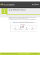
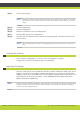
Table 1-1 Chassis Main Features
Table 1-2 SCOPIA Elite 5100 Series Features
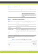
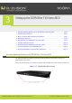
The rear panel is used for connecting the power cable, powering on and off the MCU, and for
grounding the chassis.
Figure 1-2 Rear Panel of SCOPIA Elite 5100 Series MCU
Grounding and electrostatic discharge The chassis includes an external grounding 4mm
stud as per the TUV requirement).
Cooling The chassis supports a single failed fan in the fan
tray.
Power supply
• AC power supply as the default choice.
• Universal 90-264 VAC power ports.AC power
entry includes regular IEC320-C14 filtered AC
inlet and double pole switch located in the rear.
• Thermal shutdown if the unit heats up beyond
its limits.
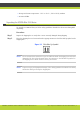
Component Description
STATUS LED Lights green to indicate normal operation. Lights red to indicate
that an error has occurred and that the Media Blade requires
resetting.
Serial connector A DB-9 connector that allows you to connect a PC terminal for local
configuration, maintenance and debugging.
100/1000 BASE-T Ethernet
connectors
RJ-45 connectors that provide the primary LAN connection for the
IP network port.
Ethernet connector
Link/Activity LEDs
The top part of each Ethernet connector contains two LED
indicators. The right LED lights green when the local IP network link
is active. The left LED lights green if the connection speed reaches
1000 Mbps, and lights orange if the connection speed reaches 100
Mbps.
RESET button Allows you to reset the Media Blade manually.
Power LED Lights green to indicate that the power is turned on.