
Installation guide

Setting up the SCOPIA Elite 5100 Series MCU | 11
RADVISION | Installation Guide for SCOPIA Elite 5100 Series MCU Version 7.5
Connecting Cables to the SCOPIA Elite MCU
Follow the safety guidelines described in the Safety Guide for the SCOPIA Elite MCU during this
procedure, and use the network and the serial cables supplied with the accessories kit.
Procedure
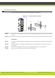
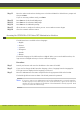
Step 1 Connect the power cable:
a. Turn off the power distribution unit (PDU).
b. On the rear side of the MCU, plug in the power cable into the AC power connector.
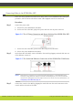
Figure 3-4 The AC Power Connector and Power Switch of the SCOPIA Elite MCU
c. On the rear side of the MCU, power on the MCU using the On/Off switch.
d. Turn on the power distribution unit (PDU).
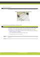
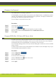
Step 2 On the front side of the MCU, connect the MCU to the switch by plugging a network cable into one
of the Ethernet connectors.
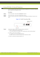
Figure 3-5 The Serial and Ethernet Connectors of the SCOPIA Elite 5100 Series
Note: Both ethernet connectors are used in dual-NIC deployments. A dual-NIC MCU raises
security by using different subnets for media and management. Use the left ethernet
connector for management and the right connector for media. For more information, see
Configuring a Dual-NIC MCU page 24.
Step 3 Connect the console to the MCU by plugging the serial cable into the serial connectors on the
console and the front side of the MCU.