SCOPIA Elite 5100 Series MCU Installation Guide Version 7.
© 2000-2010 RADVISION Ltd. All intellectual property rights in this publication are owned by RADVISION Ltd and are protected by United States copyright laws, other applicable copyright laws and international treaty provisions. RADVISION Ltd retains all rights not expressly granted. This publication is RADVISION confidential. No part of this publication may be reproduced in any form whatsoever or used to make any derivative work without prior written approval by RADVISION Ltd.
Table of Contents 1 About SCOPIA Elite 5100 Series 2 How to Prepare for SCOPIA Elite 5100 Series MCU Installation About Site Preparation...................................................................................... 3 Unpacking the SCOPIA Elite 5100 Series ................................................................. 4 Verifying the Contents ...................................................................................... 5 Inspecting for Damage ..........................................
Accessing the SCOPIA Elite 5100 Series MCU Administrator Interface............................. 15 Changing a User Password ................................................................................ 16 Changing SCOPIA Elite 5100 Series MCU Service Prefix .............................................. 16 How to Set the MCU’s Interface Languages ............................................................ 17 About Supported Languages ......................................................................
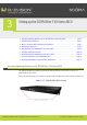
1 About SCOPIA Elite 5100 Series SCOPIA Elite 5100 Series enables multiparty multimedia conferencing services for group conferencing, distance learning, training and video telephony. The SCOPIA Elite 5100 Series consists of a 1U chassis that contains one Media Blade board. Figure 1-1 Front Panel of the SCOPIA Elite 5100 Series RADVISION | Installation Guide for SCOPIA Elite 5100 Series MCU Version 7.
Table 1-1 Chassis Main Features Grounding and electrostatic discharge The chassis includes an external grounding 4mm stud as per the TUV requirement). Cooling The chassis supports a single failed fan in the fan tray. • AC power supply as the default choice. • Universal 90-264 VAC power ports.AC power Power supply entry includes regular IEC320-C14 filtered AC inlet and double pole switch located in the rear. • Thermal shutdown if the unit heats up beyond its limits.
2 How to Prepare for SCOPIA Elite 5100 Series MCU Installation Perform procedures in this section to prepare the site and the SCOPIA Elite 5100 Series MCU chassis for installation. • About Site Preparation ......................................................................... • Unpacking the SCOPIA Elite 5100 Series..................................................... • Verifying the Contents ......................................................................... • Inspecting for Damage ............
• Storage and transit temperature: -25 C° to 70 C° (-13 F to 158 F), ambient • Acoustics 56dBA Unpacking the SCOPIA Elite 5100 Series We strongly recommend that you follow safety guidelines described in this section during MCU unpacking. Procedure Step 1 Step 2 Inspect the shipping box to verify that it is not seriously damaged during shipping. Place the shipping box on a horizontal surface paying attention to the This Side Up symbol on the shipping box.
Step 3 Cut the plastic straps. Note: Step 4 Step 5 Step 6 Step 7 Step 8 The plastic straps are tightly stretched and can hit you when you cut them. To avoid this, make sure you do not face the side of the box secured by the straps before you cut the straps. Cut the strapping tape. Open the shipping box. Take the accessories kit out of the shipping box. Take the MCU unit out of the shipping box. Carefully open the additional boxes, remove the packing material, and remove the drives and other contents.
3 Setting up the SCOPIA Elite 5100 Series MCU • Attaching Mounting Brackets on the SCOPIA Elite 5100 Series MCU .................... page 6 • Chassis Lifting Guidelines...................................................................... page 7 • What to Consider Before Installing the Brackets........................................... page 7 • Installing the Brackets ......................................................................... page 8 • Rack Mounting the SCOPIA Elite 5100 Series MCU ........
Chassis Lifting Guidelines A fully configured SCOPIA Elite 5100 Series MCU chassis weighs approximately 28.7lbs. (13kg.). The chassis is not intended to be moved frequently. Before you install the MCU, ensure that your site is properly prepared, so you can avoid having to move the chassis later to accommodate for power sources and network connections. Whenever you lift the chassis or any heavy object, follow these guidelines: • Always disconnect all external cables before lifting or moving the chassis.
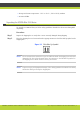
Installing the Brackets You must install the side rails into a rack with square or round holes: Figure 3-2 Mounting Holes on Rack 1 RU Rear Front 207525 1 RU Note: If you mount the side rails in holes that are not vertically aligned from side to side, you can damage the unit. Procedure Step 1 On the left and right uprights, determine the vertical position in the rack where the unit will be installed. Step 2 The unit height is 1U.
Mount Kit Description The SCOPIA Elite MCU Rack Mounting Kit contains brackets and screws as shown in Figure 3-3. Figure 3-3 SCOPIA Elite MCU Rack Mounting Rack Mounting the SCOPIA Elite 5100 Series MCU After you have installed the brackets to form a shelf, you can now mount the MCU chassis. Before mounting the chassis, read the safety guidelines described in the Safety Guide for the MCU.
Procedure Step 1 Lift the Cisco Unified Videoconferencing 5000 Series MCU chassis according to the instructions in the Chassis Lifting Guidelines page 7. Step 2 Step 3 Step 4 Step 5 Ensure the front of the chassis faces front and place the chassis on the shelf brackets. Step 6 Slide the chassis toward the front of the rack until the front of the chassis mounting brackets contact the rear of the center posts.
Connecting Cables to the SCOPIA Elite MCU Follow the safety guidelines described in the Safety Guide for the SCOPIA Elite MCU during this procedure, and use the network and the serial cables supplied with the accessories kit. Procedure Step 1 Connect the power cable: a. Turn off the power distribution unit (PDU). b. On the rear side of the MCU, plug in the power cable into the AC power connector. Figure 3-4 The AC Power Connector and Power Switch of the SCOPIA Elite MCU c.
Verifying SCOPIA Elite 5100 Series MCU Installation After you installed the MCU and performed the initial configuration of it, you need to verify that MCU is installed and configured correctly. Procedure Step 1 Step 2 Step 3 On the front panel, verify that the POWER LED is lit green. On the front panel, verify that the STATUS LED is lit green. Check the network connection by verifying that the right LED on the Ethernet connector is lit green.
4 Performing Initial Configuration of the SCOPIA Elite MCU When you finished installing the MCU, you need to perform the initial configuration during which you configure the basic features. After the initial configuration the MCU should be ready for use. • Setting the IP Address ......................................................................... • Accessing the SCOPIA Elite 5100 Series MCU Administrator Interface................. • Changing a User Password ..........................................
Procedure Step 1 Step 2 Step 3 Step 4 Connect the power cable. Start the terminal emulation application on the PC. Set the communication settings in the terminal emulation application on the PC as follows: • Baud rate: 9600 • Data bits: 8 • Parity: None • Stop bits: 1 • Flow control: None Turn on the power to the MCU. A log of the auto-boot events scrolls across the computer monitor.
Step 11 Enter the subnet mask without leading zeros at the Enter IP Mask for default device prompt and then press Enter. If you are not using a subnet mask, press Enter. Step 12 Step 13 Step 14 Step 15 Step 16 Press Enter at the Preferred DNS prompt. Press Enter at the Alternate DNS prompt. Press Enter at the DNS suffix prompt. Allow the unit to complete the reboot process. A new emulator session begins. Close the terminal emulator session.
Changing a User Password Only administrators can change a password. The SCOPIA Elite 5100 Series MCU comes with two preconfigured users: an administrator and an operator. The password for both preconfigured users is ‘password’. We highly recommend that you change the default user password for security. You can change a user password at any time. Procedure Step 1 Step 2 Step 3 Step 4 Step 5 Access the MCU Administrator interface. Select Users .
How to Set the MCU’s Interface Languages • About Supported Languages .................................................................. page 17 • Setting the MCU’s User Interface Language................................................ page 18 • Setting a Text Overlay Language.............................................................
Table 4-1 Supported Languages in the MCU Interface Language Administrator Interface Conference Control Interface Text Overlay on Conference Video English * * * Chinese (simplified) * * * Japanese * * * Portuguese * * Spanish * * Russian * * Hebrew * Setting the MCU’s User Interface Language The procedure in this section explains how to set the language of the MCU Administrator interface and the Conference Control interface. By default, the interface language is set to English.
Step 3 Select a language in the Default user interface language list. Figure 4-1 Basics Section of the Setup Tab Step 4 Select Apply at the bottom of the Setup tab. Setting a Text Overlay Language Perform the procedure in this section to set the language of the text overlay messages. The text overlay feature is set to English by default. Procedure Step 1 Step 2 Step 3 Select Configuration . Select Customization. Select the required language.
Configuring Protocols for the SCOPIA Elite MCU Set the MCU protocols by configuring it to work either with the H.323 gateway or with the SIP Proxy Server, or with both. You can change the protocol-related settings at any time without resetting the MCU. • Configuring H.323 Protocol Settings......................................................... page 20 • Configuring SIP Server Settings .............................................................. page 21 Configuring H.
Figure 4-4 The Status Map Showing the Gatekeeper Connection d. Verify that the MCU is connected to the Ethernet. e. Verify that the MCU is connected to the Gatekeeper. Configuring SIP Server Settings You can configure settings for SIP server profiles which set how the SCOPIA Elite 5100 Series MCU and the registrar interact.
Step 5 Select Locate automatically to instruct the MCU to automatically locate one of the SIP servers that are present in the domain, or Select Specify and enter the following: • An IP address or host name of the SIP server, for example ..com. Figure 4-5 SIP Protocol Section of the Protocols Tab • The communication port number of the SIP server address. The default port is 5060. • The transport connection type. The default is UDP.
b. Enter the following information: • The IP address or the host name of the SIP registrar in the IP address field. • The communication port number of the SIP registrar address. • The transport connection type for sending registration requests to the registrar according to the type supported by the SIP registrar. The default is UDP. Step 7 Select More. The Local signaling port section is displayed.
b. Enter the Administrator user name and password in the appropriate fields and select Go. The default global user name is admin. The default password is password. The Status tab of the Administrator interface opens. c. Locate the Status Map section. This section a graphic representation of the MCU chassis d. Verify that the MCU is connected to the Ethernet. e. If you registered the MCU with SIP registrar, verify that the MCU is connected to the SIP Server.
Procedure Step 1 Connect the network cable of the management subnet to the left ethernet port only, and activate the unit. Figure 4-8 Two ethernet connectors of the SCOPIA Elite MCU Note: Step 2 Step 3 Step 4 Do not connect the media subnet cable until the MCU has been reset at the end of this procedure. Access the MCU in a web browser and login. Select the Configuration tab. Select the Advanced IP (Dual-NIC) Configuration check box to expand that section of the page.
b. Enter the IP address of the management subnet’s router in the Router IP field. Note: The router IP address on this subnet must be distinct from the router on the media subnet. If both cables are connected to the same router, you must use the MCU’s VLAN functionality to send both media and management data to the same router. It will then route the media and management data to different virtual subnets (or VLANs). For more information on VLAN functionality, see the online help.
www.radvision.com About RADVISION RADVISION (NASDAQ: RVSN) is the industry’s leading provider of market-proven products and technologies for unified visual communications over IP and 3G networks.