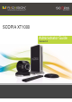
SCOPIA XT1000 Administrator Guide Version 2.
© 2000-2010 RADVISION Ltd. All intellectual property rights in this publication are owned by RADVISION Ltd and are protected by United States copyright laws, other applicable copyright laws and international treaty provisions. RADVISION Ltd retains all rights not expressly granted. This publication is RADVISION confidential. No part of this publication may be reproduced in any form whatsoever or used to make any derivative work without prior written approval by RADVISION Ltd.
Table of Contents 1 Architecture Considerations About the SCOPIA XT1000 Series .......................................................................... 1 SCOPIA XT1000 Series as Endpoints ....................................................................... 1 SCOPIA XT1000 Series as Embedded MCUs............................................................... 2 Embedded MCUs and SCOPIA XT Desktop ................................................................ 4 Firewall/NAT Support ...................
Network Settings ..................................................................................... 17 Setting the Administrator/User Password.............................................................. 18 Setting System Preferences .............................................................................. 18 Setting Date and Time............................................................................... 18 Setting the Time Zone ..................................................................
Configuring Gateway Use ........................................................................... 43 Configuring DNS Server Use......................................................................... 43 Configuring SIP Server Use.......................................................................... 43 Configuring LDAP Server Use ....................................................................... 44 Configuring ISDN Connectivity......................................................................
Video and Camera ................................................................................... 72 Contacting Support ........................................................................................ 72 RADVISION | Administrator Guide for SCOPIA XT1000 Version 2.
1 Architecture Considerations About the SCOPIA XT1000 Series The SCOPIA XT1000 Series incorporates the latest state-of-the-art video technology for room conferencing, including support for dual stream 1080p video, high quality data sharing, high quality full band audio and a high capacity embedded MCU. Among its key features, SCOPIA XT1000 delivers support for two full High Definition (HD) 1080p video streams as standard.
• High motion 720p60 capture is required. The Standard Camera does not support 60fps capture. • There are very low light conditions. In general, the Sony Camera captures better image in low light conditions. Figure 1-1 SCOPIA XT1000 Series as Endpoints SCOPIA XT1000 Series as Embedded MCUs The MCU capability is embedded in the SCOPIA XT1000 and can be activated by registering the Codec Unit serial number and product key in the XT1000 web registration page reserved to SCOPIA XT1000 purchasers.
Figure 1-2 SCOPIA XT1009/XT1209 The figure illustrates how the embedded MCU performs media processing for connected terminals regardless of their location and handle multiple conferences simultaneously. We recommend enabling the High Bandwidth Option (12Mbps) when using the embedded MCU. If the High Bandwidth option is not enabled, the MCU will send out a lower resolution according to the standard 4Mbps total bandwidth. The embedded MCU can host Standard Definition (SD) and HD endpoints simultaneously.
Embedded MCUs and SCOPIA XT Desktop Built on the SCOPIA XT1000 HD room system with its high capacity embedded MCU, the SCOPIA XT Desktop solution combines HD room system capabilities, embedded multi-party conferencing, desktop conferencing and firewall traversal. The SCOPIA XT Desktop option is delivered on a CD for installation on a separate server.
ISDN Connectivity The SCOPIA XT1000 Series supports ISDN connectivity, allowing calls from endpoints to be routed to the relevant conference using the SCOPIA BRI (Basic Rate Interface) and PRI (Primary Rate Interface) gateways. RADVISION has implemented a special pairing mechanism between the gateway and the endpoint so that ISDN dialing is very simple. After pairing the systems, the participants place ISDN calls by dialing the remote party ISDN number.
RADVISION | Administrator Guide for SCOPIA XT1000 Version 2.
2 Initial Configuration Useful Documentation When configuring the system, consult the documentation RADVISION puts at your disposal: • SCOPIA XT1000 User Guide, which explains how to operate the SCOPIA XT1000. • Release Notes, for the latest software updates. • SCOPIA XT1000 Specifications on the RADVISION web site. • RADVISION web site at http://www.radvision.com/ Registering the SCOPIA XT1000 Procedure Step 1 Step 2 Open the envelope that came with the SCOPIA XT1000.
Enabling the Software License Obtain your license key as explained in Registering the SCOPIA XT1000 page 7. Enable the software license in either way: • Locally from your terminal, by using the Remote Control Unit. • Remotely, by using a web browser to access the SCOPIA XT1000 GUI (see Enabling the License from the Codec Unit Web Page page 9). You can use software versions V1.0.x without any license. Starting from Software Version V2.
Enabling the Temporary License Work with a temporary license for a limited period of time if you cannot obtain the license key immediately. Procedure Step 1 After proceeding as described in Step 1 of Enabling the License at Setup page 8, press Start. Use the Codec Unit with full features for a time limited mode of 24 hours. The remaining activation time is shown in the system area of the screen, next to the time.
Step 3 Enter the IP address of Codec Unit in the address bar of the browser. Figure 2-4 Web Access Step 4 Once in this page select Settings > Utilities > Licenses. Figure 2-5 Web Interface RADVISION | Administrator Guide for SCOPIA XT1000 Version 2.
Step 5 Set the fields as required. Figure 2-6 Enabling the License from the Web Step 6 Step 7 Field Name Description Serial number The serial number is printed on a label affixed at the back of the Codec Unit. You can also find the serial number by pressing in any page. User code Find the user code by pressing Enable code Enter the license key you received when registering the product. in any page. Press Enable license. Press Close to close the screen.
Enabling the License from the Utilities Page Procedure Step 1 From the Main Menu page scroll to Settings and press administrator password (default is 1234). Step 2 Step 3 Scroll to Utilities. Step 4 Step 5 Enter the license key. Administrator Settings. Enter the Select Licenses. Press Save. RADVISION | Administrator Guide for SCOPIA XT1000 Version 2.
Installing and Enabling an Option License Table 2-1 SCOPIA XT1000 Software Options Reference Description MCUs 55111-00002 SCOPIA XT1000 MCU4 Option Adds 4 way 720p embedded MCU 55111-00003 SCOPIA XT1000 MCU9 Option Adds 9 way 720p embedded MCU 55111-00012 SCOPIA XT1000 MCU4->9 MCU 4 to 9 Upgrade Bandwidth and Network 55111-00004 SCOPIA XT1000 12MBPS Option Increases total bandwidth to 12Mbps 55111-00016 SCOPIA XT1000 2nd LAN port Enables 10/100 LAN port SCOPIA Desktop 88111-00001 SCOPIA XT De
Setting the User Interface Language There are four ways of setting the language of the interface: • When enabling the software license • In Page 1/6 of the Quick Setup Wizard • In Administrator settings > System > Location > General • In Settings > User settings > General. Using the Quick Setup Wizard A quick setup wizard will assist you in this first approach to the system. The quick setup will show more pages, allowing you to set some useful parameters for basic system management.
• Contrast, Brightness and Sharpness of the monitor can be configured in self-view, in order to define the display settings in optimal conditions. • If available, true pixel-to-pixel representation for Full HD resolution usually gives the better results. • Dynamic Noise Reduction, if available, may give a sharper quality of the image. • Viewing mode (Cinema or Movie), if available, may increase the visual experience. For further monitor configuration, see Configuring the Monitor page 24.
Setting Date and Time Procedure Step 1 Use the up and down arrow keys to navigate to the Day field. Press on the XT1000 Remote Control Unit to delete the date. Enter today’s date. Use the up and down arrow keys to move to the next field. Step 2 Step 3 Repeat the procedure for the Month, Year, Hour, and Minutes. (Recommended) To synchronize the system with the network time, set Internet time to Yes. Then select the relevant time zone from the drop-down list.
Step 4 The System Name field displays the name of this Codec Unit as displayed in a video conference, (e.g.: Hong Kong, or 9th Floor Conf Rm, , or NY Office). Use the XT1000 Remote Control Unit keypad to type the name. Spaces used in the name will be automatically converted to “_”. Step 5 Press Next. Network Settings The network administrator knows how to configure these settings. Contact him to get the information. Press Note: Finish to exit Quick Setup.
Setting the Administrator/User Password Set/change passwords for both User and Administrator. The default password is 1234. We recommend to change the administrator password when starting the system configuration to prevent users from inadvertently changing the settings. Procedure Step 1 From the Main Menu page scroll to Settings and press administrator password. Step 2 Step 3 Step 4 Step 5 Scroll to Utilities. Administrator settings. Enter the Select Password. Select the Administrator or User tab.
Step 3 Step 4 In the General page set the fields as required. Field Name Description Day Enter the date. Month Enter the month. Year Enter the year. Hour Enter the hour. Minutes Enter the minutes. Internet time Synchronize the system clock with the network clock, thus allowing you to align devices connected to the Internet. Press Save.
Setting Regional Data You have set some of these fields in the Quick Setup screens as they belong to the minimal setting requirements to have the system function properly. You may also modify these settings in this page. Procedure Step 1 Step 2 Step 3 Step 4 In the Administrator settings menu select System. Select Location. In the General page set the fields as required.
Pairing a XT1000 Remote Control Unit with a Codec Unit You can use the Remote Control Unit to control one or more systems in a same room, thus avoiding interferences with other Remote Control Units. To do so, enter the same code in your Remote Control Unit and in your system software. All Remote Control Units are supplied with a default code (01). Procedure Step 1 Step 2 On the Main Menu page, scroll to Settings.
Enabling the Screen Saver Procedure Step 1 Step 2 In the Main Menu page, scroll to Settings. Step 3 Using the arrow keys, scroll to Automatic screen saver to set the screen saver function to Yes. Then set the time after which the screen saver will automatically start on the display. Step 4 Press Press User settings. The General page appears on the display. Save.
Step 3 Step 4 In the General page set the fields as required. Field Name Description Default camera Specifies to which input of the Codec Unit the main camera is connected: HD-CAM 1, HD-CAM 2, DVI. The default camera is automatically activated when the system powers up. Driver Sets the camera driver for the connected camera: SCOPIA XT1000 Standard Camera or SCOPIA XT1000 Sony Camera. Camera control by far site Enables/disable control of my camera(s) by the remote terminal.
Configuring Other Video Equipment You may also access this page from a previous screen in the configuration. Procedure Step 1 Step 2 Step 3 Step 4 Step 5 In the Administrator settings menu select I/O connections. Scroll to Cameras. Select the DVI page. Set the fields as required. Field Name Description Enable Enables/disables the DVI input. Name Enter the input name. The selected name will appear in the system area of the display in addition to the input icon. Contrast Sets black level.
General Settings You may also access this page from a previous screen in the configuration. Procedure Step 1 Step 2 Step 3 Step 4 In the Administrator settings menu select I/O connections. Scroll to Monitor. Select the General page. Set the fields as required. Field Name Description Number of monitors Specifies how many monitors are connected to the Codec Unit. In case of dual configuration, sets on which monitor the menu GUI will display. HD1/HD2 - Single monitor configuration.
Graphic Adjustment You may also access this page from a previous screen in the configuration. Procedure Step 1 Step 2 Step 3 In the Administrator settings menu select I/O connections. Scroll to Monitor. Select the Graphic adjustment page. Certain monitors crop the edges of the image. Drag the sliders to the required position as explained in Adjusting the Image Size page 14. Step 4 Press Save.
Step 4 Set the fields as required. Field Name Description PIP - Position Sets the position of the small image on the monitor: upper left, upper right, lower left, lower right. PIP - Rotation Enables/disables image rotation. This setting also controls the direction in which the image rotates. Pressing pip will activate image rotation (if enabled). Fixed - The image does not change position. Clockwise - Image rotates clockwise to change position.
Step 4 Step 5 Set the fields as required. Field Name Description Enabled Enables/disables the Microphone Pod. Gain Use the slider to adjust the fixed Gain Control, setting the voice signal to the desired level. The AGC reduces the volume if the audio is strong and raises the volume if the audio is weak. Echo canceller Enable the echo canceller when working with an external microphone system that does not contain echo cancellation.
Step 4 Set the fields as required. Field Name Description Enabled Enables/disables this audio input. Gain Use the slider to adjust the fixed Gain Control ,thus setting the voice signal to the desired level. Echo canceller Enable the echo canceller when working with an external microphone system that does not contain echo cancellation. Disable this setting when working with an external mixer that handles echo cancellation.
Step 4 Step 5 Set the fields as required. Field Name Description AGC Enables/disables Automatic Gain Control. The AGC reduces the volume if the audio is strong and raises when it is weak. Noise reduction Enables/disables reduction of ambient noise in a conference room (e.g.: coughing, paper rustling, etc.). Press Save. Configuring Audio Outputs Procedure Step 1 Step 2 Step 3 Step 4 In the Administrator settings menu select I/O connections. Scroll to Audio - Outputs. Select the General page.
Step 3 Set PODS to output to Yes. Step 4 Step 5 Select Monitor > General. Step 6 Press Set Number of Monitors to HD2. Save. Upgrading to the XT1000 with Embedded MCU Procedure Step 1 Purchase the MCU4 or MCU9 option. Note: Step 2 Step 3 We recommend purchasing the High Bandwidth Option (12Mbps) when using the embedded MCU. If the High Bandwidth option is not enabled, the MCU will send out a lower resolution according to the standard 4Mbps total bandwidth.
Configuring Network Settings Configuring Preferences General Network Settings This page allows you to configure the network general settings: 1. 2. 3. 4. IPv6 is supported in addition to IPv4 . There is no IPv6-only mode. Management (HTTP, SSH, FTP) is IPv4 only (even in dual mode). Media streams in the same conference can be a mixture of IPv4 and IPv6. You can configure the IPv6 address manually or automatically. You may also access this page from a previous screen in the configuration.
Procedure Step 1 Step 2 Step 3 Step 4 In the Administrator settings menu select Networks. Scroll to Preferences. Select the Dynamic Ports page. Set the fields as required. Field Name Description Auto detect Setting to No means the Codec Unit uses the indicated ports. Setting to Yes means the Codec Unit uses ports in random mode. Recommended setting is auto-detect set to No (default). Ports Sets the range of TCP and UDP ports the system will use.
Table 2-2 Public Port List Port Number Protocol/ Port Functionality Use Type Direction Result of Blocking Port on Firewall 22 SSH TCP Secure shell Both No secure shell Remote management 23 Telnet TCP Telnet server Both No Telnet access 69 TFTP UDP TFTP client or server Both Cannot send or Send or receive receive files via files via TFTP TFTP 80 HTTP TCP Web server Both No Web server Web remote management or use 123 SNTP UDP SNTP client Both Cannot get the Internet UTC tim
Port Number Protocol/ Port Functionality Use Type 3339 3340 XML Hints TCP 1718 H.225.0/ RAS 1719 Result of Blocking Port on Firewall Description/ External Client Remote control Out Cannot send hints. iPAD SCOPIA Control and XT1000 SCOPIA Desktop Server are not operational. iPAD SCOPIA Control; XT1000 SCOPIA Desktop Server UDP H.323 call signaling to a GK for “Gatekeeper Automatic Discovery” procedure Out to the multicast IP address 224.0.0.41 (“all GK”) The H.
Step 5 Port Number Protocol/ Port Functionality Use Type 32303287 RTP and RTCP UDP 34783479 STUN UDP Press Direction Result of Blocking Port on Firewall Description/ External Client H.323 and SIP Both media (audio, video, H.224/data RTP) and media control (RTCP) No media exchanged in the H.323 or SIP call. Ephemeral UDP ports used to connect simultaneous H.323 and SIP calls media.The range can be modified by the user interface.
Step 4 Set the fields as required. Field Name Description NAT Traversal Enable this field (Yes) when the system could be located behind a firewall/NAT. If set to Yes, the fields on the page become programmable. Disable this field (No) when the system is certainly not behind a firewall/NAT, but has a public IP address. NAT Discovery Manual method of setting the system’s firewall/NAT public IP address. Enter the Public IP address for that setting.
Procedure Step 1 Step 2 Step 3 Step 4 In the Administrator settings menu select Networks. Scroll to Preferences. Select the QoS page. Set the fields as required. Field Name Description Use QoS Enable/Disable QoS. If you set Use QoS to Yes, you will provide different priority to different data stream, or guarantee a certain level of performance to a data stream. In particular, you may choose between Precedence/TOS and Differentiated Service.
Step 4 Step 5 Set the fields as required. Field Name Setting MAC address This setting cannot be changed. Automatic IP address Set to Yes (default) if the system gets its IP address automatically. If the Codec Unit is connected to the Internet and you must set up a static public IP address in the IP address field, set this field to No; the other fields in this page become programmable. IP address If the system gets its IP address automatically, indicates the IP address assigned to the system.
Procedure Step 1 Step 2 Step 3 Step 4 Step 5 In the Administrator settings menu select Networks. Scroll to GLAN/LAN. Select the Addresses page. Set the fields as required. Field Name Setting Enable Enables/disables the bandwidth option. Max. bandwidth rx (KB) Indicates the maximum receive bandwidth. Max. bandwidth tx (KB) Indicates the maximum transmit bandwidth. Press Save. Configuring MTU Parameters Settings are for GLAN and LAN connections.
Configuring Gatekeeper Use General Settings Procedure Step 1 Step 2 Step 3 Step 4 Step 5 In the Administrator settings menu select Protocols. Scroll to H.323. Select the General page. Set the fields as required. Field Name Description Name H.323 H.323 ID. Specifies the name that the terminal uses to register with the gatekeeper. Number H.323 E.164. Identifies the number that the terminal uses to register with the gatekeeper.
Step 4 Set the fields as required. Field Name Description Use gatekeeper Enables/disables the use of a gatekeeper. If No is selected, all the other fields are greyed. If Yes is selected, the Codec Unit can use the gatekeeper’s services. Automatic IP address Automatic gatekeeper discovery. The Codec Unit searches for an available gatekeeper. IP address Enter the IP address of the gatekeeper, if you do not use Automatic IP address. Use H.460 If set to Yes, the system uses H.
Step 5 Press Save. Configuring Gateway Use To configure the gateway, see Configuring Network Addresses page 38. Configuring DNS Server Use To configure the DNS server, see Configuring Network Addresses page 38. Configuring SIP Server Use Procedure Step 1 Step 2 Step 3 Step 4 Step 5 In the Administrator settings menu select Protocols. Scroll to SIP. Select the General page. Set the fields as required.
Configuring LDAP Server Use You can manage the directory using local and remote LDAP servers. The remote LDAP servers (generic, remote SCOPIA XT1000, SCOPIA iVIEW) are accessed using the H.350 protocol. Ask the LDAP remote server administrator for the values of the LDAP server fields: 1. Base 2. Filter 3. User. For the SCOPIA XT1000 remote server, the server administrator defines the User. For the SCOPIA iVIEW, the User must be agreed upon with the iVIEW server administrator.
Step 5 Set the fields as required. Field Name Description Type Allows to define the LDAP server. Address Indicates the LDAP server address. Port Indicates the port used to connect to the LDAP server. User Distinguished Name (DN) of the LDAP server user able to perform the query of all data related to SCOPIA XT1000 directory. Cannot be changed if pre-defined.
Figure 2-8 Generic Server Step 6 Press Save. Configuring ISDN Connectivity When dialing an ISDN call from SCOPIA XT1000 using a RADVISION Gateway, the user can dial the ISDN number as it is, with no IP address or delimiters. This feature is available in automatic mode when a RADVISION Gateway is present, with or without a gatekeeper. User experience is the same as using an embedded board, in all possible network configurations.
Step 5 If a gatekeeper is not present in the network, report the IP number of the gateway. If a gatekeeper is present, this number is not needed. Note: Step 6 In Solution mode (when a gatekeeper and iVIEW are available), the Codec Unit must be registered with the gatekeeper. After this setup, the user can easily place an ISDN call (as explained in the User Guide).
Step 7 By default, Automatic Service is selected and the default value of the service is set to 81. You may change this automatic service value by using the advanced interface available at Administrator settings > Calls > Preferences > ISDN page. Figure 2-12 Automatic Service Mode In certain cases, the service values must be configured more extensively - for example, when iVIEW and a gatekeeper are used in the network architecture.
Configuring Call Properties When configuring the settings the system will use for in call transmission, take into account the remote terminal capabilities. General Settings Procedure Step 1 Step 2 Step 3 Step 4 In the Administrator settings menu select Calls. Scroll to Preferences. Select the General page. Set the fields as required. Note: Step 5 The default setting indicates that the system will always try to choose the best option for the local situation.
Audio/Video Compatibility with Older Systems The Audio and Video pages list various functionalities that you may enable/disable to make the SCOPIA XT1000 compatible with an older generation of remote systems. Procedure Step 1 Step 2 Step 3 Step 4 Step 5 In the Administrator settings menu select Calls. Scroll to Preferences. Select the Audio/Video page. Set the fields as required. Press Save. Configuring IP Settings Use this page to configure IP call settings.
Configuring Video Quality In this page configure fields related to video quality. Procedure Step 1 Step 2 Step 3 Step 4 Step 5 In the Administrator settings menu select Calls. Scroll to Preferences. Select the Video quality page. Set the fields as required. Field Name Description Error resilience Set to Yes to minimize error in case of packet loss (e.g.: due to network congestion).
Securing Calls The System can manage secure videoconference sessions via encrypted connections, in both point-to-point and multipoint sessions. Procedure Step 1 Step 2 Step 3 Step 4 In the Administrator settings menu select Calls. Scroll to Preferences. Select the Encryption page. Set the fields as required. Field Name Description Accepted protected calls If encryption is set to No, and the user receives an encrypted call, the system can still accept the encrypted incoming call.
3 Maintenance Tasks System Remote Management If you enable web management, you can control the SCOPIA XT1000 via the Web: • Place a call • Change settings • Activate/deactivate options • Perform administrative tasks Procedure Step 1 Step 2 In the Administrator settings menu scroll to Utilities. Select Remote access. RADVISION | Administrator Guide for SCOPIA XT1000 Version 2.
Step 3 In the Web page set the fields as required. Note: To configure the network, contact your network administrator. Field Name Description Web management Enables/disables Web access to SCOPIA XT1000 (using Telnet via IP and ISDN connections). HTTPS Enables/disables https service, i.e. the Secure Socket Layer (SSL) function. Enable all addresses If set to Yes, enables access to SCOPIA XT1000 from any IP address in a network.
Figure 3-2 Web Interface Menu Functionality Description Latest calls Make your call by selecting a Name from the Latest calls list. Direct call Enter a number and select a profile, then select Call. Manage conference Manage an ongoing conference. Address book Manage the LDAP address book. In the current software version you can manage only the local LDAP address book. User settings Customize the interface language and the screen saver settings.
Menu Functionality Description H243 Manage the connected endpoints using H.243 commands (floor and chair control, list of participants, disconnection). Do not disturb Reject incoming calls. Mute Mute/unmute the Microphone Pod(s). Video privacy Block video transmission from your local terminal. DualVideo Activate presentation from PC (if connected). Cameras Activate camera and DVI. PIP Activate PIP. Cameras Move and/or zoom local and remote cameras.
Step 4 Set the fields as required. Note: Step 5 To configure the network, contact your network administrator. Field Name Description Download management Enables/disables downloading of firmware or patches to the Codec Unit. Enable all addresses If set to Yes, enables access to the Codec Unit from any IP address in a network. If set to No, configure Address and SubNet mask. Address Enter the IP address allowed to access the Codec Unit.
Note: You may always downgrade the system to a previous version. Call customer support for help. Procedure Step 1 Verify that the Codec Unit is switched on, and is connected to the IP network interface. (The network cable must be connected to the GLAN connector, marked 10/100/1000, on the back panel of the Codec Unit.) Step 2 Verify that the network allows communication between the Codec Unit and the PC, and that a firewall does not block TCP port 55099.
Managing the Codec Unit with AT Commands You can manage the Codec Unit from a Personal Computer using AT messages over a TCP/IP connection. The AT messages can be used for: • Initialization • Configuration • Call control and multipoint control • Control and indication • Diagnostics The message exchange between RTE and PC is based on ASCII characters. Messages are sent over a TCP socket, to the 55003 port of the RTE IP address.
Step 4 Set the fields as required. Note: To configure the network, contact your network administrator. Field Name Description AT commands management Enables/disables AT Command API for remote control. Step 5 Enable all addresses If set to Yes, enables access to the Codec Unit from any IP address in a network. If set to No, configure Address and SubNet mask. Address Enter the IP address allowed to access the system. SubNet mask Enter the SubNet mask associated with the IP address. Press Save.
Step 4 Set the fields as required. Note: Step 5 To configure the network, contact your network administrator. Field Name Description SNMP management Enables/disables SNMP use. Administrator name Enter the name of the administrator in charge of managing the SCOPIA XT1000 using SNMP. Location Enter the SCOPIA XT1000 location. Community Enter the name of the SNMP community that will support the read and write operations of SNMP management.
Step 4 Step 5 Set the fields as required. Field Name Description Enable import Enable/disable import of configuration files from iVIEW. Enable export Enable/disable export of configuration files to iVIEW. Press Save. RADVISION | Administrator Guide for SCOPIA XT1000 Version 2.
4 Troubleshooting System Management Using VNC You may use a remote VNC client installed in a PC to access the Codec Unit system and capture the GUI screenshots. You do not need a video capture card (live video content is not captured). The capture image reflects what is dynamically happening in the GUI.
Step 3 Verify that the Virtual System option is enabled and that it is possible to reach the system from the PC address. You can also enable any address or a subnet range of addresses to reach the system. Figure 4-2 Virtual System Configuration Step 4 On the PC side, you need a VNC client using standard RFB v3.3 protocol. We recommend RealVNC VNCViewer. Enter the IP address of the Codec Unit and press Enter.
• Automatically - The installed software fails to start properly for three consecutive times. The Recovery Mode is automatically invoked. If the user aborts the recovery procedure, theCodec Unit will try to start again the regular software application. • User initiated - The user restarts the Codec Unit in Recovery Mode by navigating to Administrator Settings > password > Utilities > Load default values > Recovery. Note: iVIEW is the tool used for backing up configuration files.
Step 2 (Optional) Enter the System IP address and press , or press to skip the screen. Figure 4-5 System IP Address Configuration Step 3 Once the IP address of the Codec Unit is set, you will be prompted to confirm activation of the download procedure. Figure 4-6 Download Procedure Warning RADVISION | Administrator Guide for SCOPIA XT1000 Version 2.
Figure 4-7 Download Procedure Alert Step 4 After you confirmed the procedure, the Codec Unit is ready to receive the software package. At this time, you can still safely restart the Codec Unit. Figure 4-8 System Ready to Receive Software Package Step 5 The software update package is an autoextracting file containing a specific software version (e.g.: XT1000_V1_0_5.exe). RADVISION | Administrator Guide for SCOPIA XT1000 Version 2.
Figure 4-9 Landownload Start Screen Download the package from RADVISION site to a Windows PC. Double click the package to autoextract the Landownload program. In the interface of the landownload program enter the IP address of the Codec Unit and press the Start button. Software download will begin and the Recovery Mode screen will be updated with the progress status. CAUTION: Once the Start button is pressed, do not shut down the Codec Unit until download is completed.
Using the Diagnostics Feature See the SCOPIA XT1000 User Guide for detailed information. FAQs This section lists issues that might come up while using the SCOPIA XT1000. 12 Mbps License I entered the 12Mbps license, but the system still works at a lower rate. Enable the 12Mbps rate from the configuration page Settings > Administrator settings > Calls > Preferences > General > Rate.
• Make sure your number/address is correct. • Recheck the Network Configuration, Network Preferences and H.323/SIP Proxy settings. • Make sure the Do Not Disturb function is not enabled. Check whether the GUI system area (top bar) shows an icon indicating that incoming calls are not allowed ( ). I cannot connect to a videoconference. • Check whether you dialed the correct conference number. • Check whether you are registered to the correct Gatekeeper or SIP Proxy.
Pressing and 0 simultaneously on the Remote Control Unit, brings the system back to the default auto mode. IP Address I cannot configure my IP address: • If this icon appears in the system area of the GUI, there is a bad LAN cable connection. Make sure the LAN cable is connected properly at both ends. • In the Main Menu page, press Quick setup on the Remote Control Unit. Navigate to Quick setup 6/6, and re-configure the IP address. The system does not make calls when IPv6 support is enabled.
PC Presentation I cannot send a presentation from my PC: • Make sure the VGA/DVI cable is properly connected between the PC and the Codec Unit. • From the Main Menu page, select Settings > Administrator Settings > I/O Connections > Cameras > DVI, and perform Reset. Remote Control Unit The XT1000 Remote Control Unit is no longer working.
www.radvision.com About RADVISION RADVISION (NASDAQ: RVSN) is the industry’s leading provider of market-proven products and technologies for unified visual communications over IP and 3G networks.