
Installation guide

D9412G/D7412G Operation & Installation Guide
© 2002 Radionics Page 57 43488D
D9412G/D7412G
SDI Devices
11.0 SDI Devices
11.1 Description
The D9412G/D7412G panels can support a number of accessory devices off the SDI bus using Terminals 29
through 32. Some devices include the D1255 Command Center (discussed in the previous section), the D9131A
Parallel Printer Interface Module, the D9210B Wiegand
TM
Control Interface Module, the D9133 Serial Interface
Module, and the D9133TTL-E Network Interface Module.
11.2 Installation
Consult the
Operation and Installation Guide
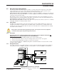
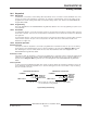
of the specific SDI device for complete installation instructions. SDI
devices connect to the panel in parallel as shown in
Table 14
.
These devices may share power with the panel or be powered by a stand-alone power source.
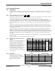
Table 14: SDI Device Connections
A stand-alone power supply powering any SDI device must also be connected to a common terminal
on the panel. Do not connect the stand-alone power supply's earth ground to Terminal 10 on the
panel.
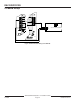
11.3 D9131A Parallel Printer Interface Module
The Radionics D9131A Parallel Printer Interface Module is a 4-wire powered device used to connect a standard
parallel printer to a panel. The D9412G can supervise three printers, and the D7412G can supervise one printer.
Each printer requires a separate D9131A Parallel Printer Interface Module. The D9131A connects to the printer
using a standard parallel printer cable.
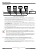
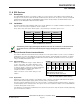
11.3.1 Switch Settings
Switches on the D9131A assign a unique address (17
to 19) to each printer. The address determines if the
printer is supervised, the printer's scope, and the area
to which the printer is assigned. See
Printer Parameters
in the
D9412G/D7412G Program Entry Guide
for a
complete description of addresses.
Table 15
shows the correct switch setting for each
address.
11.3.2 Supervision
Supervision includes proper operation of the SDI bus, proper connection of the printer cable between the printer
and the D9131A, printer paper supply, printer selected (on-line), and printer power.
The panel sends an SDI failure report to the receiver if it fails to communicate with the printer interface, and SERVC
PRINTER displays at the command center. The report to the receiver includes the address of the troubled D9131A
to indicate which printer needs service.
If an SDI device is supervised and SDI A becomes disconnected, the device may still operate normally, depending
upon environmental conditions.
D9412G/D7412G SDI Devices
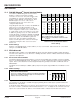
Terminal Function Wire Color Function
32 POWER + Red +12 VDC
31 DATA BUS A Yellow Data-In
30 DATA BUS B Green Data-Out
29 COMMON Black Common
SwitchPrinter
1 2 3 4 5 6
17 ON ON ON * ON ON
18
=
OFF ON ON * ON ON
19
=
ON OFF ON * ON ON
=
= D9412G only
* ON = Header and Form Feed
OFF = No Header and No Form Feed
Table 15: Printer Address Switch Settings