
Installation guide

D9412G/D7412G Operation & Installation Guide
© 2002 Radionics Page 51 43488D
D9412G/D7412G
Off-board Relays
9.2 D811 Arm Status Relay Module
The D811 Arm Status Relay Module allows the addition of a single off-board relay output to the system. Alarm
output, auxiliary relay, sensor reset, arming status, point status, alarm memory, or remote functions can be
assigned to the D811 relay output. It is not restricted to the arming status mode only.
Relay numbers for D811 not programmable:
If the D811 is connected to ZONEX 1, Terminal 28, relay number 53
must be used for the relay output. If the D811 is connected to ZONEX 2, Terminal 26 on the D9412G, relay number
117 must be used for the relay output.
D811 Modules connect as shown in
Figure 18a
and
Figure 18b
. Review section
5.0 Power Outputs
to be sure to
provide enough power for the powered devices that will be connected to the system. See
Relay Parameters
in the
D9412G/D7412G Program Entry Guide
for programming details.
D811 restricted for fire systems:
The D811 relay output is not supervised and cannot be used in fire or combined
fire/burglary installations for primary indication devices.
9.2.1 Relay Output
Each D811 relay output provides a Form C dry contact rated for 1.0 A at 12 VDC. Normally-open, common, and
normally-closed terminals are available. When an individual output is activated, there is continuity between the
normally-open and common terminals. When the output is not activated, there is continuity between the normally-
closed and common terminals.
Relay outputs may activate while programming the panel. You may wish to disconnect equipment
connected to relay outputs while performing these functions.
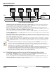
9.2.2 Installation
Install the D811 in the enclosure with the panel (see
Figure 2
) or in an adjacent enclosure NOT
MORE THAN 5 FT. (1.5 M) from the panel. Use 16 to 22 AWG wire.
Follow the procedure below to install D811 Modules in the enclosure with the panel.
1. Align the D811 Module with any of the four mounting locations in the enclosure. See
Figure 2
.
2. Use the screws provided with the module to secure it in the enclosure.
Use the D137 Mounting Bracket or D9002 Mounting Skirt to install D811 Modules in enclosures with no module
mounting locations available.
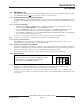
9.2.3 Wiring Connections
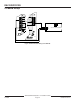
Power down the panel to connect D811 Modules as shown in
Figure 18a
and
Figure 18b
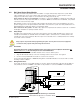
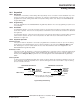
. Note that the D811 for
relay number 53 connects to ZONEX 1. The D811 for relay number 117 connects to ZONEX 2 on the D9412G.
Figure 18a: D811 Module Wiring to the D9412G
GRN
Reset Pin
Disable All Exce
p
t Batter
y
Char
g
in
g
And Pro
g
ram min
g
PERIPHERAL DEVICE CONNECTIONS
RED POWER +
YELLOW DATA BUS A
GREEN DATA BUS B
BLACK COMMON
ZONEX OUT 1
ZONEX IN 1
N.F.P.A.
St
y
le 3 .5
Si
g
nalin
g
Line
Circuits
32
31
30
29
28
27
PROG
CONN
Point 8
GND FAULT
Detect
E
N
A
B
L
E
D
I
S
A
B
L
E
ZONEX OUT 2
26
25
ZONEX IN 2
ZONEX POWER +
24
ZONEX COMMON
23
21 22
On-Board Points
5
G
N
D
A
U
X
D
A
T
A
D811 FOR RELAY NUMBER 117
5
G
N
D
A
U
X
D
A
T
A
D811 FOR RELAY NUMBER 53