
Installation guide

D9412G/D7412G Operation & Installation Guide
© 2002 Radionics Page 21 43488D
D9412G/D7412G
Installation
3.0 Installation
3.1 Before Beginning
This
Installation
section contains a general installation procedure. It provides references to other sections of the
manual for detailed instructions.
Radionics recommends a review of this manual and the
D9412G/D7412G Program Entry Guide
before beginning
the installation to determine the hardware and wiring requirements for the features that will be used.
Have the following additional documents available when reading through this manual:
•
D9412G/D7412G Program Record Sheet
•
Security System Owner’s Manual
and
Security System Owner’s Manual Supplement
•
Command Center Installation Manual (D1255, D1256, D1257, D1260, or D720)
Before beginning the installation, become familiar with the operation of the D5200 Programmer or the Remote
Account Manager (RAM IV).
3.2 Enclosure Options
Mount the control/communicator assembly in any of the Radionics enclosures listed below. Refer to the
D9412G/
D7412G Approved Applications Compliance Guide
to determine if the application requires a specific enclosure.
• D8103 Universal Enclosure (tan)
• D8109 Fire Enclosure (red)
• D8108A Attack Resistant Enclosure (tan)
3.3 Beginning the Installation
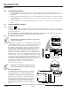
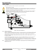
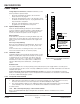
1. Mount the enclosure in the desired location. Use all five mounting holes. See
Figure 2
.
POINT CHART LABEL
MOUNTING
SKIRT HOOK
MODULE MOUNTING
LOCATIONS
MODULE
MOUNTING
LOCATIONS
TAMPER SWITCH
MOUNTING LOCATION
MOUNTING
SKIRT HOOK
SKIRT MOUNTING HOLE
MOUNTING
SKIRT HOOK
OPENINGS
LOCK DOWN TAB
BACK OF
D9412G/D7412G
Figure 2: Enclosure Mounting
2. Run the necessary wiring throughout the premises and pull the wires into the enclosure.
EMI (Electro Magnetic Interference) may cause problems:
Refer to
EMI on Long Wire Runs
in the
D9412G/
D7412G Installation and Troubleshooting Quick Reference Guide.