Network Communications System D6600 NetCom System Guide
D6600 NetCom Trademarks Microsoft®, Windows®, Windows NT® are either registered trademarks or trademarks of Microsoft Corporation in the United States and/or other countries.
D6600 NetCom Contents 1.0 1.1 1.2 1.3 1.3.1 1.3.2 2.0 2.1 3.0 3.1 3.1.1 3.1.2 3.2 3.3 3.3.1 3.3.2 4.0 4.1 Introduction........................................................................................................................................................................................... 5 Guide Organization ............................................................................................................................................................
D6600 NetCom Contents Notes: D6600 NetCom System Guide 4998122712D Page 4 © 2004 Bosch Security Systems
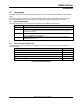
D6600 NetCom Introduction 1.0 Introduction This system guide covers the installation, operation and programming of the D6600 NetCom Network Communications System. References are made to the following control panels: D9412G, D7412G, D7212G, D9412, D9112, D7412, and D7212. Throughout the remainder of this manual, these control panels will be referred to as “Bosch Control Panels.” 1.1 Guide Organization This guide is divided into four sections. A summary of each section is detailed in the table below.
D6600 NetCom Introduction 1.3 Documentation Conventions These conventions are intended to call out important features, items, notes, cautions, and warnings that the reader should be aware of in reading this document. 1.3.1 Type Styles Used in this Guide To help identify important items in the text, the following type styles are used: Bold text Usually indicates selections that you may use while programming your panel. May also indicate an important fact that you should note.
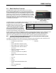
D6600 NetCom Overview 2.0 D6600 NetCom Overview The D6600 NetCom System supports data network communications. NetCom allows the D6600 Receiver to connect to Ethernet networks and process messages both to and from most networks using UDP/IP protocol. Connection to a data network can be implemented through the use of the COM4 and/or a COM1 connection from the D6600 Receiver to the D6680 Network Adapter.
D6600 NetCom Overview The C900TTL accomplishes this through dial tone and handshake simulations. The C900TTL “intercepts” the Alarm Panel’s signals and transmits them across the network to a network-enabled D6600. ** Patent numbers 5,134,644, 5,943,394 Figure 2 shows a D6600 NetCom System using a generic control panel, C900TTL-E Dialer Capture Module/network adapters, D6600 Receiver, and D6680 Network Adapters. Note: For UL Fire Listed Applications, refer to C900TTL-E Compatibility List (P/N: 4998141056).
D6600 NetCom Overview The other type of network interface for Alarm Panels is the D9133TTL-E or DX4020 Network Interface. The D9133TTL/ DX4020 is designed for use with Bosch Control Panels ONLY. No other Alarm Panel will function with the D9133TTL/DX4020. The D9133TTL/DX4020 and the Bosch Control Panels communicate using the SDI bus rather than the dialer capture method used by the C900TTL.
D6600 NetCom Overview 2.1 D6600 NetCom Pre-Installation Requirements The following pre-installation requirements must be considered BEFORE attempting to install a D6600 NetCom System. If you have any questions regarding these items, please contact the network administrator for the network you are planning to interface with or a Bosch Security Systems NetCom Engineer.
D6600 NetCom Operation 3.0 Operation 3.1 Setting Up the Host Computer If the computer you intend to use for programming the D6600, D6680, and the alarm panel network adapters is already a functioning workstation within the network you are planning to utilize, then skip this section! The host computer is defined as any computer or workstation that is properly configured and connected to the network you plan on utilizing that will manage/administer the D6600 and other devices.
D6600 NetCom Operation 5. Select the IP address tab, then click the "Specify an IP address" radio button. 6. Enter an IP address and subnet mask for the network you will be setting up, such as 202.96.168.1. Note: If you have any questions regarding the assignment of the IP address or subnet mask, see the network administrator! All devices that will be on this network must have the correct subnet mask and gateway entered. 7. Some files may have to be copied to the computer.
D6600 NetCom Operation If you have chosen to program the D6600’s initial NetCom parameters via the direct null modem serial connection, then continue on with the following steps. These steps are ONLY necessary if the host computer running the D6200 Software is connected to the D6600’s COM4 port via a direct NULL modem serial cable! 11. In Microsoft® Windows® operating system, click on the Start button and then go to Settings and Control Panel. 12.
D6600 NetCom Operation 4. Right-click on the icon and select Properties from the context menu that appears. 5. Scroll down in the ”Components checked are used by this connection:” list and highlight the “Internet Protocol (TCP/IP)” component. 6. Highlight the protocol icon for TCP/IP bound to your NIC card and click the "Properties…" button. 7. Once the dialog box appears, there will be only one tab called “General.
D6600 NetCom Operation 10. After the reboot is completed, you should perform the following check to see if the previous procedures were correctly entered. 11. Open the Run dialog box by selecting Start Programs Accessories Command Prompt. A command prompt window appears. Type ipconfig and press [ENTER]. The IP configuration for the PC is returned. The following information is displayed: Connection-specific DNS Suffix IP Address Subnet Mask Default Gateway 12.
D6600 NetCom Operation 3.2 18. A hardware tree appears showing all the devices connected to the PC in the top level. 19. Click on the small plus sign ( reveal the individual ports 20. Highlight the Communications Port (COM1) used to connect the D6200 Software to the D6600 COM4 port via a direct connect NULL Cable. 21. Right click and select Properties from the menu that appears. 22. The Communications Port (COM1) window appears with four tabs across the top. 23.
D6600 NetCom Operation COM1 COM4 COM1 1 COM4 2 7 7 D6680 Callout 1 2 3 4 5 6 7 D6680 4 3 A B C Description D6600 Receiver #1 D6600 Receiver #2 D6680 #1 D6680 #2 A/B Network switch Network switch Null modem cable Table 6: Key to Figure 4 5 6 Figure 4: D6680 Connection In Figure 4, another programming parameter that will need to be done is what we will refer to as Alternate MAC Address.
D6600 NetCom Operation 3.3 Datagram Type Differences for NetCom Software version 5.5C or greater must be installed in the network device (C900TTL-E, D9133TTL-E, or D6680) for the Datagram Type function. Software version 1.5D or greater must be installed in the DX4020. 3.3.1 Datagram 02 This datagram is only supported on the COBOX-FL version of the D6680. This datagram type is only used in the D6680.
D6600 NetCom Operation Internal IP Address Source Port Table 7 shows an example of what the NAT table remembers when packets are sent out to a destination. An 192.168.1.11 7700 outgoing packet is sent to an IP Address with both a Source 192.168.1.12 7701 and Destination port in that packet. The Destination port 192.168.1.13 7702 is the port number that the device is listening for data.
4.0 Special D6600 NetCom Applications The following are special applications that have been requested by Bosch Security Systems dealers. They are included here to assist you should you have the same requirements. If you have any questions, please feel free to contact Technical Support at (888) 886-6189. 4.1 Emulating a Direct Serial Connection Over a LAN Using D6680 Network Adapters In some applications it may be required that a direct serial connection be emulated over the network.