
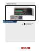
Installation guide


D6600/D6100 | Operation and Installation Guide | 2.0 Emergency Procedures
6 Bosch Security Systems | 4/05 | 4998122704F
2.0 Emergency Procedures
Section 17.0 Service Information on page 35 of this guide
contains a Service Information form. Keep this form
current and accessible to central station personnel at all
times in case of emergency.
If your D6600/D6100 Receiver becomes inoperable or
experiences trouble receiving signals:
1. Notify your supervisor.
2. Refer to Section 15.0 Troubleshooting Guide on
page 31.
3. Contact Bosch Security Systems 24-Hour
Technical Support at (888) 886-6189 for assistance
if you have a receiver spares package and need to
replace a circuit card or module.
The AC/DC Power Supply Module and
DC/DC Power Supply Module are not
field serviceable. Contact Bosch Security
Systems for service.
Disconnect power to the receiver before
removing the CPU or CPU terminator
card.
Before Calling 24-Hour Technical Support
1. Have this guide nearby and opened to Section 15.0
Troubleshooting Guide on page 31.
2. Have your spares package, the D6200
Programming Software, and the D6600/D6100
Program Entry Guide (P/N: 4998122702) nearby.
3. Know the location of the telephone line jacks for
the receiver.
4. Know the telephone numbers to the receiver’s
telephone line cards.
5. Know the exact nature of the problem you are
experiencing such as reports received, LEDs lit,
Operator Alert Buzzer sounded.
6. Have the Service Information form nearby (page 35).
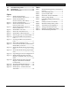
3.0 Card Functions and
Locations
3.1 D6600
3.1.1 Front Panel
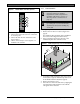
Figure 1: D6600 Communications
Receiver/Gateway (Front View)
1
2
1 – LCD - Shows up to 80 characters of information
(two lines of up to 40 characters each)
2 – Keypad - The D6600 has a 20-button keypad.
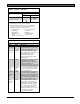
Table 2 and Table 3 show define the D6600/D6100
POWER and SYSTEM TROUBLE LEDs.
Table 2: Power LED Indications
Present Power LED Status
Green
AC Battery
Solid Blinking
Clear
X X
X
X
On
X X
X
X
Off