
Installation guide


D6600/D6100 | Operation and Installation Guide | 9.0 Input and Output Ports
.
Bosch Security Systems | 4/05 | 4998122704F 15
Table 6: Calculating Standby Current for the D6600
Device Qty Battery Standby Current UPS Standby Current
D6600 (one D6640/ D6641 Line Card) 1 800 mA 800 mA 350 mA 350 mA
Additional D6640/ D6641 Line Cards 210 mA x Qty (1 to 7) 35 mA x Qty (2 to 7)
D6672 COM1 Adapter 10 mA (if installed) 2 mA (if installed)
Total Standby Current: Total UPS Current:
The standby current required for the D6600 depends
on the number of optional cards installed in the
receiver. Table 6 helps you to calculate the D6600
standby current. The standby current required by the
D6100 is listed in Table 7.
Table 7: Standby Current for the D6100
Battery Standby Current UPS Standby Current
330 mA 180 mA
8.1.1 Minimum Standby Battery
Table 8 shows the maximum standby current for
common rechargeable battery capacities at 4 hour, 8
hour, and 24 hour standby periods. If the standby
current is larger than the value listed, you must use the
next larger capacity.
Table 8: Minimum Standby Battery Chart
Maximum Standby Current (mA) Rechargeable
Battery Capacity
4 hr 8 hr 24 hr
4 Ah 800 400 130
7 Ah 1400 700 230
8 Ah 1600 800 265
10 Ah 2000 1000 330
12 Ah 2400 1200 400
14 Ah 2800 1400 465
18 Ah 3600 1800 600
8.1.2 Minimum Standby UPS Power
The minimum UPS power required (in watts) = Total
UPS current x 120 (voltage) x required hours of
standby + 20% (storage).
9.0 Input and Output Ports
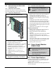
Figure 14: D6600 Back Panel Showing
Input/Output Ports
1
2
3
4
Bosch Security Systems
Fairport, NY USA
Inpu t:
100 - 120/
220 - 240V~
50 - 60 Hz
2.5 Amps
B
A
T
T
E
R
Y
1
2
5
3
4
6
1 – Output #1
2 – Output #2
3 – Input #2
4 – Ground #1
5 – Ground #2
6 – Input #1
Figure 15: D6100 Back Panel Showing
Input/Output Ports
1 2
1 2
456
3
1 – Ground #1
2 – Input #1
3 – Output #1
4 – Output #2
5 – Input #2
6 – Ground #2