
Installation guide


D6600/D6100 | Operation and Installation Guide | 8.0 Standby Power
14 Bosch Security Systems | 4/05 | 4998122704F
10. Turn the D6600 power switch on. The D6100
starts up as soon as you plug in the AC
Transformer.
11. Set the calendar and clock to the correct date and
time and program the necessary options.
12. Ensure that communication formats are correct by
having communicators send test reports to each
line connected to the receiver.
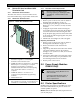
7.6 Rack Mount Instructions
Rack mounting hardware is included with the D6600,
and is available as an option with the D6100. When
mounted in a rack, plug the D6600 AC cord or the
D6100 AC transformer into an outlet inside the rack
only if the outlet is wired according to Article 760 of
the NEC. Rack mounting is required (per NFPA 72,
1-5.2.5.2) to meet the mechanical protection
requirement when using the type of AC cord provided
with the D6600/D6100. It is also required that a UL
Listed rack for fire protective service be provided when
used in UL Listed central stations.
Do not connect the D6600/D6100 to an
outlet controlled by a switch.
Install a shelf or bracket at the back of the
rack to support the D6600. The front
mounting ears cannot support the full
weight of the D6600.
7.7 Removing Power to the Receiver
1. Remove battery power.
2. Turn off the AC power on the D6600 or unplug
the D6100 AC transformer.
3. Unplug the AC cord from the outlet.
Do not try to restart the D6600/D6100
with a fully discharged battery. Reconnect
after you apply power. To prevent deep
battery discharge, use a D135A Low
Battery Cutoff Module. Refer to the
D135A Installation Guide (P/N: 74-
06499-000) for more information.
If programmable Output 1 or 2 is
activated by automation failure, you
cannot clear Output 1 or 2 by pressing
[ACKNOWLEDGE].
8.0 Standby Power
During a loss of AC power, the receiver automatically
switches to standby power. External batteries or an
uninterruptible power supply (UPS) provides standby
power. As long as there is adequate standby power, the
receiver’s operation is not interrupted, even if the
power loss occurs during signal processing. When
power supervision is enabled and a loss of AC power
occurs, the primary reporting devices (such as printers
and computers) show AC FAIL and the D6600/D6100
power indicator starts blinking. When AC power
restores, the power indicator stops blinking and
reporting devices show AC RESTORE.
8.1 Connecting External Batteries
Do not connect an external battery
charger to the D6600/D6100.
Use the terminal on the rear panel to connect an
external DC power source. During AC power outages,
the external DC source supplies power to the receiver.
Use a 12 VDC lead-acid battery for external backup
power.
Only use approved stationary standby batteries for UL
applications. Battery wiring must run from the receiver
through the UL Listed rack, exit the rack through a
conduit connection, and terminate at a UL Listed
battery enclosure suitable for the size and number of
batteries used for UL applications.
Table 5: Battery Voltage Display
Battery Voltage Display during
AC power outage
Display if no
battery when
AC power is
restored
Above 11.5 V
Battery OK
11.5 V to 10.2 V
Battery Low
Below 10.2 V
Battery Bad
Battery
Missing