
Installation guide


D6600/D6100 | Operation and Installation Guide | 7.0 Installation
.
Bosch Security Systems | 4/05 | 4998122704F 13
7.0 Installation
7.1 All Installations
Install the D6600/D6100 Communications
Receiver/Gateway according to the National Electrical
Code (NEC), NFPA 70, the National Fire Alarm Code,
NFPA 72, and the local Authority Having Jurisdiction
(AHJ).
7.2 UL Installations
UL Standard 827 requires that any central
station listed for NFPA 72, Central Station
Protective Signaling, UL Central Station
Burglary or Police Station Connect
Service must have a redundant receiver
on the premises to use if the primary
receiver malfunctions.
UL Standard 827 also states that you must be able to
switch from one receiver to a standby receiver within
30 sec, and repair the faulty receiver and return it to
service within 30 min.
NFPA 72 requires that if more than eight telephone
lines are used, the receiving equipment must be
completely duplicated so switchover can be
accomplished in 30 sec (per NFPA 72-1996 4-
5.3.2.2.1.1).
7.3 Burglar Alarm Applications
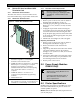
Figure 13: Location of D6100 Battery Terminals
and D6600 Battery Connector
1
2
3
4
Bosch Security Systems
Fairport, NY USA
Input :
100 - 120/
220 - 240V~
50 - 60 Hz
2.5 Amps
B
A
T
T
E
R
Y
1 2
D6100
D6600
B
A
T
T
E
R
Y
Receivers are not shown to scale.
Install the D6600/D6100 Receiver according to UL
Standard 827 for Central Station Burglar Alarm
Systems. Use in a central station that has backup AC
power (per UL 827) to supervise certificated accounts.
Terminals for connection of external batteries are on
the rear of the receiver (Figure 13).
7.4 Fire Alarm Applications
The D6600/D6100 Receiver can be used for Central
Station Protective Signaling when it is installed and
used in compliance with NFPA 72 and ANSI/NFPA
70. Installation limits for digital alarm communicator
receivers (DACR) are under the local AHJ.
7.5 Installation Check List
1. Check each receiver card to see that it is correctly
positioned in the card guides at the top and bottom
of the enclosure. Also confirm connections did not
loosen during shipment (D6600 only).
2. Ensure the earth ground is connected and
grounded through the AC inlet.
3. If you are installing additional line cards, install the
terminator cards now (D6600 only).
4. After installing additional line terminator cards,
install the line cards (refer to Section 4.1.2 Card
Installation on page 10).
5. You might also want to install the line terminator
card(s) from your spares package(s). If there is a
malfunction, you can quickly switch over to the
replacement card (refer to Section 4.1.2 Card
Installation on page 10).
You can install spare line terminator
cards. Do not install spare line cards.
6. Connect four or six conductor telephone cord(s) to
the RJ11C jack(s) of the desired telephone line(s).
Plug the other end of the modular telephone
cord(s) into the telephone jack on the appropriate
line terminator card(s).
7. Connect the appropriate country-specific AC
transformer wiring leads to the AC terminals on
the rear of the D6100.
8. Plug the AC cord (D6600 only) into a correctly
wired 120 VAC, 60 Hz or 220 VAC, 50 Hz outlet
(standard AC outlet).
9. Plug the AC transformer into the correctly wired
wall receptacle that matches the voltage of the
transformer.
Ensure a switch does not control the
outlet.