
Installation guide


D6600/D6100 | Operation and Installation Guide | 4.0 D6600 Specific Cards
.
Bosch Security Systems | 4/05 | 4998122704F 11
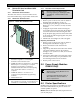
Figure 10: Inserting the D6645 Line Terminator
Card
4
2
1
3
1 – Alignment slot
2 – Alignment guide tab
3 – D6645 Line
Terminator card
4 – D6600 Back plate
6. Slide the card into the enclosure so the alignment
guide (Item 2, Figure 10) tab on the back of the
terminator card (Item 3) inserts into the alignment
slot (Item 1) in the back of the D6600’s back plate
(Item 4) circuit board.
Figure 11: Securing the D6645 Line Terminator
Card
4
3
2
2
1
1 – D6645 Line Terminator Card
2 – Bracket screws (top and bottom)
3 – Empty slot
4 – D6600
7. Mount the terminator card (Item 1, Figure 11 on
page 11) in an empty slot (Item 3, Figure 11) of the
receiver cabinet (Item 4, Figure 11) by securing the
bracket screws at the top and bottom (Item 2,
Figure 11) of the terminator card to the mounting
rails at the top and bottom edges of the cabinet.
Ensure the screws are tight.
8. Repeat this process for all additional terminator
cards.
Do not install spare line cards and do not
connect line cards to the spare terminator
cards.
9. Connect appropriate telephone line cords to the
telephone line jack on the terminator cards.
Installing Telephone Line Cards
1. Install the telephone line terminator card(s) (refer
to Installing Telephone Line Terminator Cards on page
10).
2. Open the display door on the receiver.
One telephone line card is installed in the receiver
when shipped from the factory.
3. Slide a line card into the slot next to the installed
line card.
4. Remove the appropriate snap-in covers from the
front of the panel.
5. Close the front panel.
6. Program the line card if necessary.
When the line card is initialized (as indicated by a
printer report), the settings in the line card
programming section automatically load into the
card.
7. Connect telephone lines to the line card
4.1.3 Telephone Line Monitoring Voltage
The receiver continuously monitors the telephone line
voltage. Normal operating voltage ranges from
1.8 VDC to 2.5 VDC. Any voltage above 2.5 VDC
causes the line to appear good (restoral) and an
indication appears if any voltage is below 1.8 VDC.