
Installation guide


D6600/D6100 | Operation and Installation Guide | 4.0 D6600 Specific Cards
10 Bosch Security Systems | 4/05 | 4998122704F
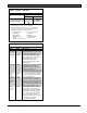
Figure 8: D6640/D6641 LED Descriptions
OL/LF
1
2
3
4
1
2
3
4
1 – Flashes green when an incoming call rings.
2 – Glows green when the receiver is online with
an incoming call.
3 – Glows red when the line card detects a line
fault condition.
4 – LED is off and ready to receive signals or is
disabled in the software.
4.1.2 Card Installation
Remove power to the receiver when
removing, replacing, or installing
telephone line cards or telephone line
terminator cards (refer to Section 7.7
Removing Power to the Receiver on
page 14).
Discharge static electricity from your body
by touching the receiver’s internal frame
(unpainted section) before handling any
circuit card.
Installing Telephone Line Terminator Cards
1. Remove the rear slot cover (Item 3, Figure 2 on
page 8).
One telephone line terminator card is installed in
the receiver when shipped from the factory.
2. Insert a terminator card in the slot next to the
installed telephone line terminator cards.
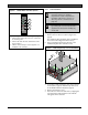
Figure 9: Removing the top cover of the D6600
1
2
3. To replace a failed terminator card, remove the six
screws (Item 1, Figure 9). Hold the top metal cover
of the D6600 and lift it off (Item 2, Figure 9).
4. Remove the defective card.
5. Insert the new card in the same slot by aligning the
top and bottom of the terminator card with the
card guides in the enclosure.