D6600/D6100 Operation and Installation Guide EN Receiver/Gateway
D6600/D6100 | Operation and Installation Guide | Trademarks Trademarks Microsoft®, Windows®, Windows NT® are either registered trademarks or trademarks of Microsoft Corporation in the United States and/or other countries.
D6600/D6100 | Operation and Installation Guide | Contents . Contents 1.0 2.0 3.0 3.1 3.1.1 3.1.2 3.1.3 3.1.4 3.2 3.2.1 3.2.2 3.2.3 4.0 4.1 4.1.1 4.1.2 4.1.3 4.2 4.2.1 4.2.2 4.2.3 5.0 6.0 7.0 7.1 7.2 7.3 7.4 7.5 7.6 7.7 8.0 8.1 8.1.1 8.1.2 9.0 9.1 9.1.1 9.1.2 9.2 Introduction ................................................. 5 Emergency Procedures ................................... 6 Card Functions and Locations....................... 6 D6600................................................................
D6600/D6100 | Operation and Installation Guide | Contents 15.0 16.0 17.0 Troubleshooting Guide.................................31 Specifications ...............................................34 Service Information.......................................
D6600/D6100 | Operation and Installation Guide | 1.0 Introduction . 1.
D6600/D6100 | Operation and Installation Guide | 2.0 2.0 Emergency Procedures Section 17.0 Service Information on page 35 of this guide contains a Service Information form. Keep this form current and accessible to central station personnel at all times in case of emergency. If your D6600/D6100 Receiver becomes inoperable or experiences trouble receiving signals: 1. Notify your supervisor. 2. Refer to Section 15.0 Troubleshooting Guide on page 31. 3.
D6600/D6100 | Operation and Installation Guide | 3.0 Card Functions and Locations . Table 3: System Trouble LED System Trouble LED Status Solid Red Clear No System Trouble Any System Trouble* * Refer to Appendix B: D6600/D6100 Internal Messages in the D6600/D6100 Computer Interface Manual (P/N: 4998122703). The following items cause system trouble. Depending on the supervision setting, the items indicated by ** might cause system trouble.
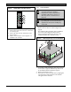
D6600/D6100 | Operation and Installation Guide | 3.0 3.1.3 Card Functions and Locations Rear View The D6600 has input and output pin connector sockets for up to eight line cards, network option (if installed), and one CPU card. It also has slots for connecting these cards to their corresponding terminator cards. Figure 2: D6600 Communications Receiver/Gateway (Rear VSiew) 1 2 3 4 Bosch Security Systems Fairport, NY USA 1 2 3 4 B A T T E R Y Input: 100 - 120/ 220 - 240V~ 50 - 60 Hz 2.
D6600/D6100 | Operation and Installation Guide | 4.0 D6600 Specific Cards . 3.2 D6100 3.2.1 Front Panel Figure 4: Figure 6: D6640/D6641 Line Card 1 D6100 Communications Receiver/ Gateway (Front View) 2 1 – Liquid crystal display (LCD) - Displays up to 80 characters of information (two lines of up to 40 characters each) 2 – 23-button keypad Table 2 and Table 3 on page 6 define the D6600/D6100 POWER and SYSTEM TROUBLE LEDs. 3.2.
D6600/D6100 | Operation and Installation Guide | 4.0 Figure 8: D6640/D6641 LED Descriptions 4 1 3 2 2 3 1 4 D6600 Specific Cards 4.1.2 Remove power to the receiver when removing, replacing, or installing telephone line cards or telephone line terminator cards (refer to Section 7.7 Removing Power to the Receiver on page 14). Discharge static electricity from your body by touching the receiver’s internal frame (unpainted section) before handling any circuit card.
D6600/D6100 | Operation and Installation Guide | 4.0 D6600 Specific Cards . Figure 10: Inserting the D6645 Line Terminator Card 7. 4 8. 3 2 Do not install spare line cards and do not connect line cards to the spare terminator cards. 9. 1 1 – Alignment slot 2 – Alignment guide tab 6.
D6600/D6100 | Operation and Installation Guide | 5.0 4.2 D6610 CPU Card and D6615 CPU Terminator Card 4.2.1 D6610 CPU Card Connection The CPU card connects to the user interface on the front of the D6600 using a 50-pin ribbon cable socket. 4.2.2 D6615 CPU Terminator Card Figure 12: D6615 CPU Terminator Card 1 2 3 4 1 – Alignment Guide - Stabilizes the connection and acts as a guide for connecting the terminator card to the CPU card.
D6600/D6100 | Operation and Installation Guide | 7.0 Installation . 7.0 Installation 7.1 All Installations Install the D6600/D6100 Communications Receiver/Gateway according to the National Electrical Code (NEC), NFPA 70, the National Fire Alarm Code, NFPA 72, and the local Authority Having Jurisdiction (AHJ). 7.
D6600/D6100 | Operation and Installation Guide | 8.0 10. Turn the D6600 power switch on. The D6100 starts up as soon as you plug in the AC Transformer. 11. Set the calendar and clock to the correct date and time and program the necessary options. 12. Ensure that communication formats are correct by having communicators send test reports to each line connected to the receiver. 7.6 Rack Mount Instructions Rack mounting hardware is included with the D6600, and is available as an option with the D6100.
D6600/D6100 | Operation and Installation Guide | 9.0 Input and Output Ports .
D6600/D6100 | Operation and Installation Guide | 9.0 9.1 UPS Monitoring through CPU Programmable Input Ports Use the CPU programmable input port to connect the external UPS to the D6600/D6100 for power monitoring. Connect the monitoring port from the UPS to matching pins on the D6600/D6100 CPU Programmable Input/Output port (Figure 14). Wiring must run from the receiver through the UL Listed rack, exit the rack through a conduit connection, and terminate at the external UPS for UL applications.
D6600/D6100 | Operation and Installation Guide | 10.0 D6600/D6100 Operation . 10.0 D6600/D6100 Operation 10.1 Process Flow Sort and Display Events by Time/Date To view individual events in the Event Database on the D6600 LCD. 10.1.1 Event Database The Event Database stores all trouble conditions and alarm messages that occur in the D6600/D6100. The maximum number of events stored in the database is 20000.
D6600/D6100 | Operation and Installation Guide | 10.0 D6600/D6100 Operation Display Current System Troubles The default User ID is 6200 and the default password is 6200. To review a log of trouble conditions that occurred: 2. D6600 D6100 M/E ENTER 2. D6600 D6100 3. D6600 D6100 M/E ENTER 1. = the most recent trouble condition message. The total number is in brackets. 4. D6600 D6100 5. D6600 D6100 6. D6600 D6100 CAN CANCEL 3.
D6600/D6100 | Operation and Installation Guide | 10.0 D6600/D6100 Operation . 10.1.2 Receiver Handshake and Kiss-Off The telephone line dialed by the communicator connects to a line card in the D6600/D6100. The line card detects ringing voltage, answers the incoming call, and sends a programmed series of handshake tones. The communicator detects the expected handshake and transmits its message. The receiver sends the kissoff after the receiver receives and understands the communicator’s message.
D6600/D6100 | Operation and Installation Guide | 10.0 D6600/D6100 Operation 10.1.7 Buzzer Operation 10.2 In the Manual Mode, an Operator Alert Buzzer sounds when a message is received until you press [ACKNOWLEDGE]. The buzzer operation is programmable and can be disabled when the receiver is programmed for the Automatic Mode.
D6600/D6100 | Operation and Installation Guide | 10.0 D6600/D6100 Operation . 10.3 Operating in Manual Mode 10.4 Keypad Menu Operation If all reporting devices (such as printers and computers) fail, the D6600/D6100 reverts to Manual Mode until a device returns to service. 10.4.1 Log In When the D6600/D6100 receives signals while in Manual Mode: The Operator Alert Buzzer sounds. D6600 1. 1. D6100 Shuts off the operator alert buzzer 2. D6600 D6100 M/E MENU Enter password.
D6600/D6100 | Operation and Installation Guide | 10.0 D6600/D6100 Operation D6600 10.4.3 Event Buffer Display D6600 D6600 D6100 D6100 Shows event buffer contents in the order the events are received. No more system troubles remain D6100 SYSTEM TROUBLE Refer to Section 15.0 Troubleshooting Guide on page 31 for more information. If multiple lines of text are received, 10.4.
D6600/D6100 | Operation and Installation Guide | 10.0 D6600/D6100 Operation . 10.4.7 Skip Current Automation Event 4. Use this option to skip the current Automation event. 1. 5. D6600 F D6600 D6100 3 3 D6600 D6100 M/E ENTER D6100 FUNCTION D6600: 2. Enter password. D6100: D6600 default password: 6600 D6100 default password: 6100 3. D6600 M/E 6. D6600 1 D6100 ENTER to D6600 D6600 3 2 D6100 D6100 1 7. 4. D6600 5. D6600 D6100 M/E ENTER Selects the line to test.
D6600/D6100 | Operation and Installation Guide | 10.0 D6600/D6100 Operation 10.4.9 Clear Pending Events 10.5 Use this option to clear all pending events. The D6600/D6100 Receiver software monitors and reports when a call group of receiver lines cannot receive signals. The receiver cannot process signals if its incoming telephone lines are in trouble, if other communicators have the line tied up, or if the line card is inoperative. The receiver interprets these conditions as busy time. 1.
D6600/D6100 | Operation and Installation Guide | 10.0 D6600/D6100 Operation . 10.6 Two-Way Audio When using the D6600/D6100 for Two-Way Audio (TWA) verification, use the Flash or Hold option according to the central station Private Branch Exchange (PBX) system, taking the D6600/D6100 off line in a short period. If a PBX is not used, connect a regular telephone in parallel with the incoming telephone line.
D6600/D6100 | Operation and Installation Guide | 10.0 D6600/D6100 Operation 10.6.2 Two-Way Audio Modes of Operation • Transfer: D6600/D6100 transfers the incoming line to another line; a flash operation occurs at the end of the alarm signal. The receiver dials the line programmed at Transfer Phone Number (refer to Menu Items 3.1.4.18 Flash [x 100ms] and 3.1.4.19 Transfer Phone Number in the D6600/D6100 Program Entry Guide [P/N: 4998122702]).
D6600/D6100 | Operation and Installation Guide | 11.0 Network Communications (D6600 Only) . 11.0 Network Communications (D6600 Only) The D6600 Central Station Communications Receiver/Gateway NetCom system supports data network communications. NetCom allows the D6600 Receiver to connect to Ethernet networks, and process messages both to and from most networks in user datagram protocol (UDP) or internet protocol (IP). Use a COM4 or a COM1 connection from the D6600 Receiver to connect to the network adapter.
D6600/D6100 | Operation and Installation Guide | 12.0 No Data Received Reports Figure 18: D6600 NetCom System Connection Diagram - D9133TTL-E and Bosch Control Panels 2 7 8 12.2 9 3 5 13 10 Description No Data Received The D6600/D6100 generates the message shown in Figure 19 if one or more of the following occur: 4 12 12.1 If a message is garbled (incorrect checksum or inconsistent message rounds) due to a noisy telephone line or other difficulty, the receiver withholds the kissoff tone.
. D6600/D6100 | Operation and Installation Guide | 13.0 Using the Central Station Automation System with the D6600 13.0 Using the Central Station Automation System with the D6600 Figure 21: D6600 System – Standard/Network Automation 1 If using a D6600, connect a central station automation system computer to the COM3 port (automation computer port) on the D6615 CPU Terminator Card with a null-modem cable. Refer to the D6600/D6100 Computer Interface Manual (P/N: 4998122703) for additional information.
D6600/D6100 | Operation and Installation Guide | 14.0 Central Station Tips 14.0 Central Station Tips 14.1 Back-up Receiver Spare circuit boards and receivers should be available at the central station. Keep a spare kit on hand. UL Listed central stations monitoring burglary or fire alarms must have a spare receiver available for activation within 30 sec. 14.2 Computer Interface Keep spare cards for all receiver components. Keep a spare CPU terminator card in the central station. 14.
D6600/D6100 | Operation and Installation Guide | 15.0 Troubleshooting Guide . 15.0 Troubleshooting Guide The D6600 consists of several plug-in assemblies that you can easily replace in the field (components and controls on individual assemblies are shown starting in Section 3.0 Card Functions and Locations on page 6). Do not attempt to repair individual assemblies. Return any failed assemblies to Bosch Security Systems for testing and repair.
D6600/D6100 | Operation and Installation Guide | 15.0 Troubleshooting Guide Table 11: Hardware Troubleshooting Guide (continued) Problem Operator alert buzzer cannot be silenced. D6200 cannot connect to the D6600. Symptom Solution • System stalled • Check watchdog LED on the inside of the door behind the keypad. LED must flash for a running system. A solid light does not indicate a running system. Reset power cycle of the D6600 if stalled.
D6600/D6100 | Operation and Installation Guide | 15.0 Troubleshooting Guide . Table 11: Hardware Troubleshooting Guide (continued) Problem D6200 cannot connect to the D6600 through a network connection. Symptom D6200 network connection is defective, missing, or has incorrect network cable. Solution • • • • D6200 cannot connect to the D6600 through a network connection. D6200 network connection is defective, missing, or has incorrect network cable.
D6600/D6100 | Operation and Installation Guide | 16.0 Specifications 16.0 Specifications Table 12: D6600/D6100 Specifications Dimensions (H x W x D) D6600 D6100 Weight Rack mount (2U) 18 cm x 48.3 cm x 49.5 cm (7.0 in. x 19.0 in. x 19.5 in.) Standalone 18 cm x 45.0 cm x 49.5 cm (7.0 in. x 17.75 in. x 19.5 in.) Rack mount (1U) 9.0 cm. x 37.5 cm. x 25.5 cm (3.5 in. x 19 in. x 10 in.) Standalone 9.0 cm. x 30.5 cm. x 25.5 cm (3.5 in. x 12.0 in. x 10 in.) D6600 8.
D6600/D6100 | Operation and Installation Guide | 17.0 Service Information . 17.0 Service Information (EMERGENCY DATA SHEET) In a central station emergency, use this information to contact the necessary people and enable Bosch Security Systems Customer Service Personnel to help you with your emergency. Have your supervisor provide you with the following information: Supervisor’s Name: Emergency Telephone #: Telephone Co. Repair Service Telephone #: Contact: Power & Light Co.
Bosch Security Systems 130 Perinton Parkway Fairport, NY 14450-9199 Customer Service: (800) 289-0096 Technical Support: (888) 886-6189 © 2005 Bosch Security Systems 4998122704F