
Installation guide


D6600 NetCom
C900TTL-X Configuration
D6600 NetCom System Guide
© 2001 Radionics Page 73 46542C
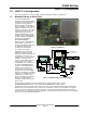
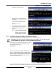
7.4 Overview of Onboard Outputs
The C900TTL-X has 4 open-collector outputs onboard:
• Output 1: Active (shorted to ground) as long as the CPU is functioning
normally. If the CPU fails to operate or the CPU loses power, output 1 will be
open.
• Output 2: Active as long as the D6600 Receiver is communicating properly,
and open when the D6600 is not communicating to the C900TTL-E.
• Output 3: Active whenever the C900TTL-X is in Intercept Mode.
• Output 4: Controlled by command from the D6200 software (default is open).
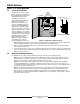
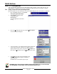
7.5 Overview of Onboard Terminal Strip
The following list describes the functions of the C900TTL’s Power Terminal Strip:
• +12 V: Connect regulated 12 volt DC power to this terminal and the -12 V
terminal. This power may be supplied by a separate power supply, battery, or
Auxiliary power from the Control/ Communicator.
• -12 V: Return terminal for the 12 VDC power supply (earth ground
connection).
10K EOL
Resistor
Figure 34: C900TTL-X
Onboard Terminal Strip
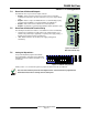
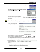
7.6 Setting the Dipswitches
A 10-position dipswitch programs the C900TTL.
The programming is dependent on the application
and dialer format of the Alarm Panel that it is to be
connected to.
1 2 3 4 5 6 7 8 9 10
ROCKER DOWN
O
F
F
ONOFF
Figure 35: C900TTL-X Dip Switches
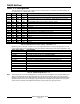
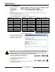
Switch positions 1,2,3, & 4 all work together to program the dialer format into the C900TTL.
The C900 must emulate a phone line and a digital receiver. It must therefore be programmed to
know what format it will be receiving from the alarm panel.