
Installation guide


D6600 NetCom
C900TTL-X Configuration
D6600 NetCom System Guide
46542C Page 72 © 2001 Radionics
7.2 Physical Installation
The C900TTL-X is static sensitive.
Make sure you touch earth ground
before handling the circuit board.
This will discharge any static
electricity from your body.
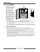
A Door Bracket (P/N: 40182C) is
included for mounting the
C900TTL-X on the door of the
enclosure. Mounting instructions
can be found in the C900TTL-E
Operation and Installation Guide
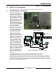
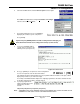
(P/N: 41123). Figure 33 shows the
C900TTL-X mounted in a separate
enclosure (D2203). It is possible to
mount the C900TTL-X in a D8103
or D8109 enclosure, but additional
mounting hardware is required.
When using either method,
Radionics suggests running the
ground wire to the enclosure
before handling the circuit board.
Wire
Knockouts
Mounting
Hole
Mounting
Hole
C900TTL-E
Retainer Holes
Ground Tab
Retainer
Tabs
Mounting
Holes
Circuit board
Enclosure
SUPPORT POST ASSEMBLY
O
F
F
1 2 3 4 5 6 7 8 9 10
PANEL
TELCO
C OUT 4 OUT1OUT2OUT3
IN3 IN2
IN1
C
I-12V+
Figure 33: C900TTL-X in D2203 Enclosure
1. While holding the ground wire (or using a ground strap), install the circuit board. Insert the two support posts
into the circuit board retainer holes as shown in the Support Post Assembly diagram.
2. Slide the top of the circuit board into the two retainer tabs. Once in the retainer tabs, the circuit board will
rest on the two support posts.
3. Secure the bottom of the enclosure by screwing the bottom two holes through the support posts and through
to the control retainer holes. Once the circuit board is installed, be sure to connect its ground wire to the top
hinge of the panel enclosure.
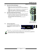
7.3 Overview of Onboard Inputs
The C900TTL-X has 3 inputs monitored by A/D converters. They serve the following functions:
• Input 1: Used as an EOL supervised loop. If the D6200 host computer enables Input status reports, then
any voltage above 3.33 VDC is reported as an open condition to the host. Any voltage below 1.66 volts is
reported as a short. Input 1 must be EOL terminated with a 10 K resistor.
• Input 2: Used for Intercept Inhibit. If input 2 goes above 1.66 volts, then the C900TTL-X is immediately
forced into Fallback Mode for a minimum of 2 minutes. Input 2 must go low for at least 5 seconds to be
considered low. Input 2 is intended for connection to a fire bell to force fire reports to be sent digitally. If input
2 is unused, it may be left disconnected.
• Input 3: Used for Intercept Override. If input 3 goes above 1.66 volts for 5 seconds, then the C900TTL-X
enters into Fallback Mode. If input 3 goes low, then the C900TTL-X will return to Intercept Mode. If this is
driven by ground start relay output, the C900 will stay in Fallback, except when the dialer wishes to dial.
Input 3 cannot force an intercept if the C900 is in Fallback due to error, command, or input 2 high. If unused,
this may be left disconnected.