
Installation guide


D6600 NetCom
D9133TTL Configuration
D6600 NetCom System Guide
© 2001 Radionics Page 53 46542C
5.0 D9133TTL-E Configuration
This section details how to correctly install, configure and program a Radionics D9133TTL-E.
5.1 Network Enabling a Radionics 9000 Series Panel using a D9133TTL-E
The D91331TTL-E is a SDI bus
device for use with the Radionics
9000 Series Control/
Communicators. The D9133TTL-
E is used for bi-directional
communications over Ethernet
networks that are typically used
for event reporting, PC9000
monitoring, and RAM remote
programming.
A Door Bracket (P/N: 40182C) is
included for mounting the
D9133TTL-E on the door of the
enclosure. Mounting instructions
can be found in the D9133TTL-E
Operation and Installation Guide
(P/N: 41124).
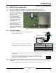
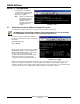
Figure 17: D9133TTL-E Serial Interface Network Adapter
5.2 Physical Installation
1.
Remove AC and battery power from the Radionics 9000
Series Control/Communicator.
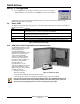
D9133TTL-E
PERIPHERAL DEVICE WIRING
RED
YELLOW
GREEN
BLACK
POWER +
DATA BUS A
COMMON
DATA BUS B
31
30
32
29
Control/Communicator
9000 Series
Control/Communicator
D9133TTL-E
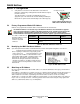
SDI PWR (Terminal 32) SDI PWR
SDI A (Terminal 31) SDI A
SDI B (Terminal 30) SDI B
SDI COM (Terminal 29) SDI COM
2.
Wire the D9133TTL-E to the Control/ Communicator as
indicated in Table 16: D9133TTL-E Wiring Connections.
Table 16: D9133TTL-E Wiring Connections
3.
Connect an Ethernet cable from the network to be utilized by the Modular Jack labeled Ethernet on the
D9133TTL-E.
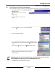
4. Set the SDI address for the D9133TTL-E to “88”. This is accomplished by placing a
jumper across position 8 on the D9133TTL-E. SDI Address 88 is reserved for 9000
Series Alternate Communication Functions.
1 2 4 8
88
Note: The D9133TTL-E address configuration is read only at D9133TTL-E power-up. If the address configuration is
changed while the D9133TTL-E is powered, the power must be cycled so that the D9133TTL-E can reconfigure
its address.
5. Reconnect AC and battery power to the Control/Communicator and power up the system.