
Installation guide


Bosch Security Systems | 11/03 | 39352E
EN | 62
D9124 | Operation & Installation Guide |
Appendix B: D9142 24 VDC Power Supply
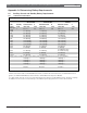
Table 28: D9124 24 V Power Supply Specifications
Power Input
Nominal: 120 VAC, 60 Hz, 360 VA
Power Outputs
24 V indicating and initiating devices with a minimum operating voltage greater than 18.9 VDC
or a maximum operating voltage less than 28 VDC can be damaged or fail to operate.
One Output: 4 A maximum
DC Output Voltage (AC applied): 22 VDC minimum, 28 VDC maximum
DC Output Voltage (No AC): 18.9 VDC minimum, 27 VDC maximum
Low Battery
Voltage
Trouble Threshold: 22 VDC minimum, 24.1 VDC maximum
Restoral Threshold: 24.2 VDC minimum, 26.5 VDC maximum
Load Shed
Voltage Trouble Threshold: 18.9 VDC minimum, 20.5 VDC maximum
Voltage Restoral Threshold: 23.1 VDC minimum, 24.7 VDC maximum
AC Line Fuse F1
Type 3 AG: 4 A, 250 V Slow Blow. Bosch Security Systems (P/N: 57-01338-004)
Supervision
Output Relay
Form C, rated for 2 A @ 12 or 24 VDC
Environmental
Considerations
Operating Temperature: 0°C to +50°C (+32°F to +122°F)
Relative Humidity: 5% to 85% at +30°C (+86°F) non-condensing
Batteries
Use the following 12 V sealed lead/acid batteries: 7 Ah, 12 Ah, 14 Ah, 17.2 Ah, 24 Ah, 36 Ah,
or 38 Ah
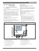
B.1.2 Default Trouble Output Settings
Five trouble conditions can activate the relay. See the
Supervision Relay Configuration DIP Switch (S1) on the
D9142 (Figure 29).
NO AC: 120 VAC power failure annunciation. Do not
use for 24 V fire applications. The D9124 Control Panel
provides this function.
NO AC FUSE: Fuse F1 failure.
NO DC: Power output failure due to grounds or shorts
on the output circuit.
BATT TEST: Causes fault if battery test circuit fails.
LOW BATTERY: Battery voltage low or battery
missing.
The factory settings are shown in Figure 30.
B.1.3 Specifications
Figure 30: D9142 Factory Switch Settings
ON
OFF
NO AC
NO AC FUSE
NO DC
BATT TEST
LOW BATT
S1