
Installation guide


EN | 55
D9124 | Operation & Installation Guide |
Bosch Security Systems | 11/03 | 39352E
12.16 Ground Fault
If a D9124 System detects a ground fault, considered a
high impedance fault to earth ground of approximately
100 kΩ or less, the control panel’s command center
shows SERVC GND FAULT. Use the following
procedure as a general guideline in identifying and
isolating the cause of the earth ground fault.
Read the following procedure carefully
before trying to identify the cause of the
ground fault.
12.16.1 Isolating Earth Ground Faults
Terminals 6 and 7 are not energized.
Terminal 8 is energized.
To isolate earth ground faults:
1. With this safety measure in mind, first verify the
ground fault is, or is not on the battery terminals
(Terminals 4 and 5). Use a digital voltmeter (DVM)
and a 13-in. jumper wire. As a reference point, when
a D9124 Control Panel is not in a ground fault
condition, a voltage reading between Terminals 9
and 10 is 6.5 VDC to 6.8 VDC.
2. Place the DVM on a DC volts scale. Connect the
positive (red) lead of the DVM to Terminal 10 (earth
ground) and negative (black) lead to Terminal 9
(common) of the control panel.
Stop if voltage reading is between
13.70 VDC and 13.88 VDC.
3. This voltage reading means the ground fault can be
in one of the control panel power circuits such as the
Battery, or Aux.
Remove both battery wires from Terminals 4 and 5
simultaneously. If the voltage across Terminals 9 and
10 changes to 6.5 VDC to 6.8 VDC (indicating a
normal reading), the ground fault is on the battery
wire(s). Locate and remove the ground fault.
4. If the voltage across Terminals 9 and 10 still
measures between 13.70 VDC and 13.88 VDC,
reconnect the battery wire(s) back to Terminals 4
and 5 and go to Step 5.
12. Troubleshooting
Stop if voltage across Terminals 9 and 10
reads 0 VDC.
5. This voltage reading indicates the ground fault is on
any of the control panels’ common terminals.
Remove both battery wires from Terminals 4 and 5.
If the voltage across terminals 9 and 10 changes to
6.5 VDC to 6.8 VDC, the ground fault is on this
battery is negative side. Locate and remove the
ground. If voltage across Terminals 9 and 10 does
not change, reconnect both battery wires to
Terminals 4 and 5 and go to Step 6.
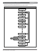
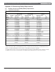
6. With the DVM still connected between Terminals 9
and 10, use Table 23 to determine which terminal
grouping has the ground fault.
Terminals 6 and 7 are not energized.
Terminal 8 is energized.
7. Once the voltage is determined, remove the wire(s)
from the terminals listed and verify the voltage on
Terminals 9 and 10 is approximately 6.5 VDC to
6.8 VDC. If the voltage does not measure within
this range after removing the suspected wire,
continue to check the remaining wires connected to
the terminal group.
If voltage at Terminals 9
and 10 is:
Ground fault is on Terminal:
0 VDC 4, 9, 12, 15, 18, 21, 23
(D9412G only), and/or 29, 6
and/or 7
approximately 1.7 VDC 6 and/or 7
approximately 2.5 VDC 11, 13, 14, 16, 17, 19, 20,
and/or 22,
approximately 7.0 VDC
fluctuating
30 and/or 31
approximately 7.6 VDC
fluctuating
1 and/or 2
approximately 11 VDC
to12 VDC
25 (D9412G/D7412G only),
26 (D9412G only), and/or 28
(see Step 5)
approximately 13.8 VDC 3, 5, 8, 24 (D9412G only),
and/or 32
Table 23: Terminal Grouping Ground Fault