
Installation guide


Bosch Security Systems | 11/03 | 39352E
EN | 52
D9124 | Operation & Installation Guide |
12. Troubleshooting
12.10 Checking Shielded Cable
If improperly installed, shielded cable can create
problems rather than solve them.
To check shielded cable for proper installation:
1. Remove the drain wire for the shield from Terminal
10.
2. Meter the drain wire for continuity to Terminal 10
(earth ground). If there is continuity, find and
remove the foreign ground on the drain wire.
3. Reconnect the drain wire to Terminal 10.
4. Meter the shield at the far end of the cable (last
POPIT location on data expansion loops) for
continuity to a ground reference. If there is no
continuity, find and repair the open in the shield.
Solder and tape all connections.
12.11 Battery and Power Reports
You can program the control panel to transmit both
Battery and AC Power Status Reports (see the D9412G/
D7412G Program Entry Guide).
If Battery or AC Power Reports are a problem:
1. Make sure the control panel power supply is not
overloaded. Review Section 7.0 Power Supplies and
Section 12.14 Overloaded Power Supply.
2. Verify there is at least 16.5 VAC on Terminals 1 and
2. The outlet the transformer is plugged into should
meter between 110 VAC and 120 VAC.
3. Confirm the output for the transformer connected to
Terminals 1 and 2 is rated for 16.5 VAC and at least
40 VA.
4. Disconnect the transformer from Terminals 1 and 2
and meter the battery at Terminals 3 and 4. A fully
charged battery shows approximately 13.8 V.
5. Make sure the battery is a 12 V sealed lead-acid
type. It should be rated at 7 Ah or greater,
depending on the NFPA classification of the
installation.
6. If it takes longer than 60 seconds to detect a missing
battery, make sure there is a good earth ground
connection. Also make sure there are no external
devices that can induce voltage.
12.12 Watchdog Reset Reports
The control panel sends a Watchdog Reset Report
whenever the control panel CPU is interrupted and
restarts its normal operating sequence. The on-board
buzzer sounds briefly during the Watchdog Reset. The
control panel returns to normal operation immediately
after resetting.
The most common cause of CPU interruption and
Watchdog Reset Reports is static discharge to the
control panel. Static discharges may also corrupt the
control panel's program. The D9124 displays PARAM
FAIL at the command centers and sends a Param
Cksum Fail Report if the program is corrupted.
Shorting Terminals 3, 6, 7, 8, 24, or the programming
connector to ground can also cause a Watchdog Reset.
Remove the short to continue normal operation.
A single isolated Watchdog Reset Report does not mean
the control panel must be replaced. If experiencing
frequent reports, contact Bosch Security Systems
Customer Service for help.
Touch Terminal 10 first: If the on-board buzzer sounds
briefly when the control panel is first touched, any static
charge being carried is being discharged to the control
panel. The control panel can generate Watchdog Reset
and/or Param Fail events. Always touch Terminal 10
(control panel’s earth ground connection) before
beginning work on the control panel.
12.13 Runaway Reports to the Receiver
Using D8128 or D8128A instead of the D8128D
OctoPOPIT Module can cause Runaway Reports to the
receiver on AC failure. Make sure you replace all D8128
or D8128A OctoPOPITS with the D8128D Module.
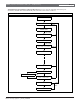
12.14 Overloaded Power Supply
If the load on the control panel's power supply exceeds
capacity, it follows a routine to protect itself and the
battery. The control panel sends reports to the central
station at several points during this routine.
Keep in mind the AC power remains at Terminals 1 and
2 throughout the scenario that follows:
• The control panel operates normally with a good
battery, AC is present at Terminals 1 and 2, and
auxiliary power load is under 1.4 A.
• The combined load on Terminals 3, 6, 7, 8, 24, and
32, accessory connector, and programming
connector exceeds and remains above 1.4 A. Device
failure or premises wiring ground faults may cause
the increased load.
• The yellow Charging Status LED turns on,
indicating the control panel is drawing on the
battery to support the increased load.
• The battery begins to drain. When voltage drops to
12.1 V, the control panel sends a Low Battery Report
and turns on the red Low Battery LED.
• When the battery drops to 10.2 V, the control panel
disconnects it to protect it from deep discharge.