
Installation guide


EN | 51
D9124 | Operation & Installation Guide |
Bosch Security Systems | 11/03 | 39352E
12.8 D8125 POPEX Data Expansion Loops
Electromagnetic interference (EMI), excessive
resistance, or intermittent grounds, shorts, or opens on
the data expansion loop can cause erratic or intermittent
functioning of points. If EMI is a problem, see Section
12.9 EMI on Long Wire Runs.
AC induction on the data expansion loops must be less
than 1.0 VAC. If EMI is not suspected as the cause of
the problem, follow the procedure in Section 12.8.1 to
find the source of problems on the data expansion loop.
You can also use the Zonex Point Identification Validation
Process (P/N: 43049) for a detailed procedure and
worksheets to identify and validate all points.
12.8.1 Metering the Loops
Before performing the following procedure to meter the
data expansion loops, check Table 22 to verify the
correct gauge wire was used for the length of the data
expansion loops.
When metering the loop, monitor it long enough to
observe an intermittent problem.
To meter the data expansion loop without connected
POPITs:
1. Disconnect the loop from the POPEX Module.
2. Twist the positive and then the negative wires
together at each POPIT location so the positive and
negative wires are continuous to the last POPIT
location.
3. At the last POPIT location, twist the end of the
positive wire to the negative wire to form one
continuous loop.
4. Meter the loop for continuity from the point where
it connects to the POPEX Module. Resistance for
the entire loop must be less than 60 Ω. If there is no
continuity, find and repair the open on the loop.
5. Still metering for continuity, untwist the negative
and positive wires at the last POPIT location. If the
meter does not show an open condition, find and
repair the short on the loop.
6. Twist the positive and negative wires at the last
POPIT location together.
7. Meter the loop for continuity to Terminal 10 (earth
ground). If there is continuity, find and remove the
foreign ground on the loop.
8. Meter the loop to Terminal 10 for AC voltage. AC
induction on data expansion loops must be less than
1 VAC. Try using shielded cable to reduce AC
induction if the AC voltage exceeds 1 VAC.
12.9 EMI on Long Wire Runs
EMI can cause problems on long wire runs for serial
devices such as command centers and POPITs. Using
shielded cable reduces the effect of this interference.
Some potential sources of noise on a long wire run
include:
• Radio or television transmitter site
• Amateur radio operator’s transmitter site
• Computer network system
• Heavy machinery (large electrical motors)
• PBX telephone system
• High voltage electrical equipment or transformers
such as arc welders, certain medical and dental
equipment, and so on
• Public service office using radio communications
(fire department and police department, and so on)
• Close proximity to electrical lines, telephone
cabling, or fluorescent lighting fixtures
There are many other possible sources of noise. If noise
is a problem, use shielded wire. Connect the drain wire
from the shielded cable to Terminal 10 on the control
panel.
The drain wire must have continuity from the control
panel to the last device on the wire run. If the cable is
cut to install devices between the last device and the
control panel, make sure you reconnect the drain wire to
insure continuity to the last device.
If continuity is not maintained between the control
panel and the last device, the shielded cable can
aggravate potential noise problems rather than eliminate
them. Connecting the drain wire to ground at other than
Terminal 10 on the control panel can also produce
problems. Do not connect the drain wire to any other
ground source.
12. Troubleshooting
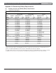
Table 22: Data Expansion Loop Wire Specifications
Maximum Length of all Data Expansion Loops Combined
AWG Length in meters (feet)
22 548 (1800)
20 881 (2890)
18 1402 (4600)
16 2231 (7320)
14 3551 (11,650)