
Installation guide


EN | 47
D9124 | Operation & Installation Guide |
Bosch Security Systems | 11/03 | 39352E
12.4 Command Centers
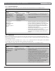
Table 18 identifies problems that can occur at command centers and describes how to troubleshoot them.
12.5 Phone Line
Phone line problems that are not corrected can choose the control panel to go into communications failure. The
D9124 can be programmed to monitor one or two phone lines. Refer to the D9412G/D7412G Program Entry Guide for
programming instructions.
If the phone line monitor is enabled, SERVC PHONE LINE #1 (#2 if two lines are used) appears in the command
center display when the control panel detects a problem on the phone line.
Table 19 identifies problems that can occur with phone lines and describes how to troubleshoot them.
12. Troubleshooting
Table 18: Command Centers
Problem Diagnosis Solution
•
More than one command
center has the same
supervised address.
•
Use a supervised address in one command center only or use
a different supervised address for each command center.
Command centers show
erratic behavior. For
example, the pip that
confirms you pressed a
key echoes.
•
Data connections (yellow
and green wires) on one or
more command centers are
reversed, or only one wire
is connected.
•
Verify the yellow and green data wires are correctly connected
on all command centers.
NO AUTHORITY
displays at the
command center when
you enter your
passcode to perform a
function.
•
Check the User Interface section of the program to be sure the
function is enabled for the authority level assigned to the
passcode in the Passcode Worksheet section of the program.
•
Check the Passcode
Worksheet section of the program
confirm the passcode is assigned to the area where you are
attempting to perform the function.
•
Check the Passcode
Worksheet section of the program to see
if the passcode is restricted by a user window.
•
Check the Area Parameters section of the program confirm the
area in which you are attempting to perform the function is
turned on.
Table 19: Phone Line
Problem Diagnosis Solution
SERVC PH LINE #1
(or
#2
if two lines are
used) appears in the
command center
display.
The control panel phone line
monitor detects a phone line as
faulted.
•
Verify the telephone cord is correctly connected to the phone
jack and the control panel.
•
Verify the Ground Start Jumper is in the correct position.
•
If using a ground start phone line, verify a D136 relay is
correctly installed in the Ground Start Relay socket.
•
Verify the phone jack (RJ31X or RJ38X) is wired correctly. The
incoming phone line must be wired to Terminals 4 and 5. The
in-house phone system must be wired to Terminals 1 and 8.
•
Verify all telephones are on-hook. Leaving a telephone on hold
after the other party hangs up creates an off-hook condition.
Verify there are no phones are on hold.
•
If completing the previous steps does not restore the phone
line, meter the line. If your readings are below 3.0 VDC,
contact your telephone company repair service.