
Installation guide


Bosch Security Systems | 11/03 | 39352E
EN | 46
D9124 | Operation & Installation Guide |
12.3 Control Panel Programming
Become familiar with the basic operation of the D5200 programmer before attempting to program the control panel
(see the D5200 Operation Manual).
Table 17 identifies problems that can occur at the control panel and describes how to troubleshoot them.
12. Troubleshooting
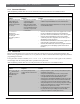
Table 16: continued
Problem Diagnosis Solution
SERVC GND FAULT
appears in
command center displays.
The control panel detected an earth
ground fault.
Follow the steps in
Section 12.16.1 Isolating
Ground Faults.
See also Connecting Earth Grou
nd
in the
D9412G/D7412G Operation and Installation
Guide
.
SERVC KEY PAD
appears at other
command centers connected to the
control panel, and the control panel
transmits an SDI Failure Report to
the receiver.
The control panel lost contact with
a supervised command center.
Press [ESC] to silence the buzzer. The displays
clear when contact with the missing command
center restores.
SERVC 9210 #n
appears at the
other command centers connected
to the control panel and the control
panel transmits an SDI Failure ##
Report to the receiver.
The control panel lost contact with
a D9210B Access Interface
Module.
Check the wiring for opens, grounds, or shorts.
SERVC PH LINE #1 (SERVC
PH LINE #2)
appears in
command center displays.
The control panel detected a phone
line fault.
See
Section 12.5
Phone Line
. Also, refer to Phone
Line Monitor in the
Telephone Connections
section
in the
D9412G/D7412G Operation and Installation
Guide
for a complete description.
SERVC PRINTER
appears in
command center displays.
The control panel lost contact with
a supervised printer.
Press [ESC] to silence the buzzer. The displays
clear when contact with the missing printer restores.
Table 17: Control Panel Programming
Problem Diagnosis Solution
The programmer is not correctly
connected to the control panel.
•
Verify the data/power cord is plugged into the
communicator port on the D5200.
•
Verify the data/power cord is plugged securely
into the control panel programmer connector.
•
Check each conductor in the data/power cord
for continuity.
The programmer displays
PLUG IN
PANEL
when you press [SEND] or
[RECEIVE].
AC induction through the
on-board point sensor loops, the
DATA bus, or the ZONEX bus.
•
Verify a proper earth ground at Terminal 10.
•
Disconnect on-board point sensor loops, data
bus
(Terminals 30 and 31), and ZONEX bus
(Terminals 25 to 28).
After plugging in the programmer,
the control panel transmits SDI
Trouble Reports for supervised SDI
devices (such as command centers
and printer interface modules). All
SDI devices stop operating.
The control panel handler was not
entered within 30 seconds of
plugging in the programmer.
•
Enter the control panel handler within 30
seconds of plugging in the programmer.
•
Once the SDI reports are generated, sending
or receiving a handler or disconnecting the
programmer returns the SDI devices to normal
operation.