
Installation guide


Bosch Security Systems | 11/03 | 39352E
EN | 40
D9124 | Operation & Installation Guide |
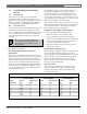
9. Telephone Connections
When using a primary and backup device within a
Route Group #, the control panel makes two attempts
on the primary phone line using the Primary Device #
as programmed. If these two attempts fail, the control
panel switches to the secondary phone line using the
Backup Device # as programmed. This pattern
continues for a total of ten attempts. After ten
unsuccessful attempts, the control panel generates a
Comm Fail event for the given Route Group #.
9.12.3 Watchdog Feature
The D928 watchdog circuit monitors the control panel’s
CPU for proper operation. If the CPU fails, the buzzer
on the D928 sounds, as does the sounder on the control
panel. This sounder cannot be reset when the CPU fails.
The D928 stops sounding only when the control panel
CPU returns to normal operation.
9.12.4 Installing the D928
Mounting
Mount the D928 on the lower right side of the enclosure
using the screws provided with the switcher.
Wiring
The D928 has two flying leads. The green lead monitors
AC power. The black lead provides surge protection for
the two incoming phone lines. The black lead is also the
ground reference for the AC LED.
1. Connect the green lead from D928 to Terminal 1.
2. Connect the black lead from D928 to Terminal 9.
Phone Connections
1. Plug one end of the ribbon cable (provided with the
D928) into J4 on the D928. Plug the other end into
the accessory connector on the control panel.
2. Plug one end of the D162 (61 cm [2 ft.]) phone cord,
provided with the D928, into J3 on the D928. Plug
the other end into Telco on the control panel.
3. Plug one end of a D161 (2.1 m [7 ft.]) or D162 (61 m
[2 ft.]) phone cord into J1 on the D928. Plug the
other end into the RJ31X or RJ38X for the primary
phone line.
4. Plug one end of a D161 or D162 phone cord into J2
on the D928. Plug the other end into the RJ31X or
RJ38X for the secondary phone line.
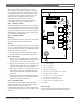
9.12.5 D928 Status LEDs
Four LEDs, mounted on the front edge of the D928
Module, show the status of AC power for the control
panel, status of the two phones lines, and
communication failure (Figure 25). When programmed
and operating normally, only the green AC power status
LED is lit.
AC Power LED
The green AC Power Status LED lights when there is
AC power at Terminals 1 and 2 on the control panel.
1 - Connect to ACCESSORY CONNECTOR with
ribbon cable.
2 - Green to Terminal 1
3 - Black to Terminal 9
4 - AC Power LED (green)
5 - Phone jack to primary phone line - RJ31X
6 - Primary Fail LED (yellow)
7 - Phone jack to secondary phone line
8 - Secondary Fail LED (yellow)
9 - Phone jack to TELCO Connector
10 - Communications Fail LED (yellow)
11 - Buzzer
Figure 25: D928 Dual Phone Line Switcher
+
+
1
4
3
2
5
6
7
8
9
10
11