
Installation guide


EN | 39
D9124 | Operation & Installation Guide |
Bosch Security Systems | 11/03 | 39352E
9. Telephone Connections
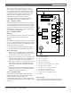
9.11.1 Relay Installation
Power down the system before inserting the D136 relay
into the GND START socket. The relay socket is in the
lower left corner as shown in Figure 23. The plug-in
relay is shorter than the socket it plugs into. It can be
installed in either the left or right end of the socket.
Do not rely on relay labelling. Do not rely on the
labelling to install D136 relays. Check for the side with
three pins. The three pins go on the top side of the
socket.
Incorrect insertion does not damage the
relay or the control panel, not the related
circuits do not function properly. Do not
insert a ground start relay if the ground start
jumper is in the loop start position (see
Figure 24
).
9.11.2 Phone Monitor Select Jumper
The Phone Monitor Select jumper is above the Telco
connector point at the lower left corner of the control
panel. Set it in the ground start position (Figure 24).
9.12 D928 Dual Phone Line Switcher
9.12.1 Description
The optional D928 Dual Phone Line Switcher lets the
control panel transmit reports over two separate phone
lines. The control panel monitors both lines. If a signal
is generated and the control panel senses a line is bad, it
attempts to use the other phone line to send the
message. If trouble is detected, the control panel keeps
the faulty phone line in memory.
Set the ring count above 2 on answering machines.
The control panel RPS line monitor feature may not
operate correctly if an answering machine with a ring
count of less than two is connected to a phone line used
by the D928 Module.
Two phone lines are required in UL Listed fire
applications.
9.12.2 Operation
See Phone in the D9412G/D7412G Program Entry Guide
for phone supervision and reporting options. Set the
Two Phone Lines prompt to YES to use the D928.
When the D928 is installed, the control panel alternates
between Phone Line 1 and Phone Line 2 to send its first
report. For example, on day one the control panel
attempts to first communicate on Phone Line 1. On day
two, the panel switches and attempts to communicate on
Phone Line 2.
Any time the control panel resets or powers down/up,
the next reported event always attempts to call out on
Phone Line 1 first.
If Phone Line 2 is not in service on Day 2, the control
panel switches to the primary phone line to send the
report.
With the D928 Dual Phone Line Switcher installed, the
control panel uses two phone lines (primary and
secondary) to dial up to four phone numbers.
Figure 23: Terminals 7 and 8 Relays and Ground
Start
1 - Top
2 - Left
3 - Bottom
4 - Gnd Start
5 - SW Aux
6 - ALT alarm
Note: The D136 relays are inserted with the three
pins towards the top side.
1
2
3
6
5
4
Figure 24: Phone Monitor Select
1 - Loop start position 2 - Ground start position
GROUND FAULT DETECT
Enabled
Disabled
LOOP
PHONE MONITOR SELE
GROUND START
Requires
Relay # D136 in
Ground
Start Socket
GND
1
2