
Installation guide


Bosch Security Systems | 11/03 | 39352E
EN | 38
D9124 | Operation & Installation Guide |
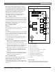
9.5 Phone LED (Red)
The red Phone LED lights when the control panel seizes
the phone line, and remains lit until the control panel
returns the phone line. See Figure 22 for the location of
the red LED.
9.6 Operation Monitor LED (Green)
The green Operation Monitor LED indicates the central
processing unit (CPU) is working. When the CPU is
operating normally, the LED flashes 0.5 second on, 0.5
second off.
The green LED also serves as a ring indicator. The LED
is located on the lower right side (see Figure 22). When
there is ring voltage on the phone line (the phone is
ringing), the green LED flickers at a faster rate for the
duration of each ring. Ring voltage must reach a
minimum of 45 VAC before the system detects it.
9.7 Dialing Format
You can program the system to use DTMF or pulse
dialing. See Phone Parameters in the D9 412G/ D7412G
Program Entry Guide.
9.8 Phone Line Monitor
The control panel has a built-in phone line monitor that
tests the phone line for voltage. If the D928 Dual Phone
Line Switcher is used to connect two phone lines to the
control panel, the control panel monitors both lines. The
normal voltage on a telephone line is approximately
48 VDC (24 VDC for some phone systems). The phone
line monitor senses trouble when the voltage on the line
falls below 3.0 VDC.
If the monitor senses trouble, it starts a programmable
phone line trouble timer, which continues to run as long
as the monitor senses trouble. It resets to zero when the
control panel senses a normal line. If the timer reaches
the delay time in the Phone Supervision program item,
it begins a phone line trouble response. Programming
determines what the response is. See Phone Parameters in
the D9412G/D7412G Program Entry Guide.
Any time the D9412G/D7412G uses the phone line to
make a call or is on-line with RPS, it ceases to monitor
the phone line during this process. Once the phone line
on the D9412G/D7412G is no longer in use, it begins
once again to monitor the phone line.
Bad line may test OK. The telephone line monitor uses
voltage levels to test the phone line status. In some
instances, a given telephone line can be out of service
without affecting the voltage on the line. The phone line
monitor can not recognize this trouble condition.
9.9 Called Party Disconnect
Telephone companies provide “called party disconnect”
to allow the called party to terminate a call. The called
party must go on hook (hang up) for a fixed interval
before a dial tone is available for a new call. This
interval varies with telephone company equipment.
D9124 firmware allows for “called party disconnect” by
adding a 35-second “on hook” interval to the dial tone
detect function. If the control panel does not detect a
dial tone in 7 seconds, it puts the phone line on hook for
35 seconds to activate “called party disconnect,” goes off
hook and begins a seven-second dial tone detect. If no
dial tone is detected, the panel dials the number anyway.
Each time the number is dialed, the control panel
records this as an attempt.
9.10 Communication Failure
After ten attempts to reach the receiver, the control
panel goes into communication failure. The control
panel clears any reports in its phone buffer and a
COMM FAIL RTE # event is generated, which appears
in the display at command centers. A trouble sounder
can be programmed to annunciate at the command
centers.
One hour after the COMM FAIL RTE # is generated,
the control panel attempts to send this event, if
programmed. If the COMM FAIL RTE # event is the
only event in the queue and cannot reach the central
station, the command centers do not turn on the trouble
sounder again.
If the D928 Dual Phone Line Switcher is used, the
D9124 makes a total of ten attempts before going into
communication failure.
9.10.1 Enhanced Communication
The D9124 Control Panel transmits events over the SDI
bus to a D9133TTL-E Network Interface Module. For
more information on enhanced communications
capabilities, refer to RADXAUX1 in the D9 412G/D7412G
Program Entry Guide.
9.11 Ground Start
Some telephone systems require a momentary ground
input to initiate dial tone. To interface with a ground
start system, insert a D136 plug-in relay into the GND
START socket and set the Phone Monitor Select jumper
to the GND START position.
Do not use ground start in NFPA
applications. You cannot use ground start
telephone systems for NFPA central station
protective signaling or remote station
applications.
Connect Terminal 10 to an earth ground so the ground
start phone systems operate properly on the D9124.
9. Telephone Connections