
Installation guide


EN | 37
D9124 | Operation & Installation Guide |
Bosch Security Systems | 11/03 | 39352E
9. Telephone Connections
9.1 Registration
The Bosch Security Systems D9124 Control Panel is
registered with the FCC under part 68, for connection to
the public telephone system using an RJ31X or RJ38X
jack installed by the local phone company.
An RJ31X jack can be modified to become an RJ38X
jack by placing a jumper wire between Terminals 2 and
7.
9.2 Notification
Do not connect registered equipment to party lines or
coin-operated telephones. Notify the local telephone
company and supply them with the following
information before connecting the control panel to the
telephone network:
• The particular line to which the control panel will
be connected
• The make (Bosch Security Systems), model (D9124),
and serial number of the control panel
• FCC registration number and ringer equivalence for
the control panel. Refer to Part 68 in Section 1.4
FCC Rules or to the label on the D9124 for this
information
9.3 Location
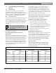
To prevent signal jamming, wire the RJ31X or RJ38X
jack before the in-house phone system to support line
seizure (Figure 21). Install the jack on the street side of
the phone switch, wired ahead of any PBX equipment.
Line seizure provides for a temporary interruption of
normal phone usage while the control panel transmits
data. After installation, confirm the control panel seizes
the line, acquires dial tone, reports correctly to the
receiver, and releases the phone line to the in-house
phone system.
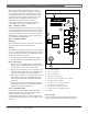
9.4 Phone Cord Connection
Connect one end of a D161 (2.1 m [7 ft.]) or a D162
(61 cm [2 ft.]) telephone cord to the Telco cord
connector located on the bottom left corner of the
control panel (Figure 22). Then, connect the other end to
the RJ31X or RJ38X jack.
To supervise the phone cord, use an RJ38X jack.
9. Telephone Connections
Figure 21: D166 (RJ31X Jack) Wiring
1 - RJ31X or RJ38X jack
2 - Telco connector block
3 - Premises telephone
4 - TIP
5 - Outside Telco
6 - RING
7 - Strap across Terminals 2 and 7 creates RF38X
8 - RING (red)
9 - TIP (green)
4
5
8
4
58
4
5
8
1
1
1
T1
T
R
R1
2
7
5
4 6
8
2
3
1
9
7
1 - Telephone cord connector
2 - Telephone LED (red)
3 - Operation monitor LED (green)
Figure 22: Telephone Connector and LED and Operation Monitor LED Connections
PHONE
LED
RED
ON WHEN
COMMUNICATING
OFF WHEN IDLE
GRN
E
N
A
B
L
E
D
I
S
A
B
L
E
1211 13 1514 16 1817 19 2120 22
GROUND START
Requires
Relay # D136 in
Ground
Start Socket
1
2
3